
Catalyst metering device

a metering device and catalyst technology, applied in chemical/physical/physical-chemical stationary reactors, chemical/physical processes, constructions, etc., can solve problems such as mechanical wear of equipment and unstable reactor operations, and achieve the effects of avoiding mechanical wear of valves, fewer leakages in metering devices, and reducing the chance of metering devices getting jammed

Active Publication Date: 2014-06-03
TOTAL RES & TECH FELUY
View PDF9 Cites 2 Cited by
  • Summary
  • Abstract
  • Description
  • Claims
  • Application Information

AI Technical Summary

Benefits of technology

The present invention provides a catalyst metering device with a longer lifetime, optimal reaction conditions, and fewer leakages and stick-ups in its use. This device allows for precise and controlled dosing of abrasive and viscous catalyst slurry while avoiding mechanical wear of its valve.

Problems solved by technology

This induces mechanical wear of equipment and unstable feeding of catalyst leading ultimately to unstable reactor operations.

Method used


Image

  • Catalyst metering device
  • Catalyst metering device
  • Catalyst metering device

Examples


Embodiment Construction

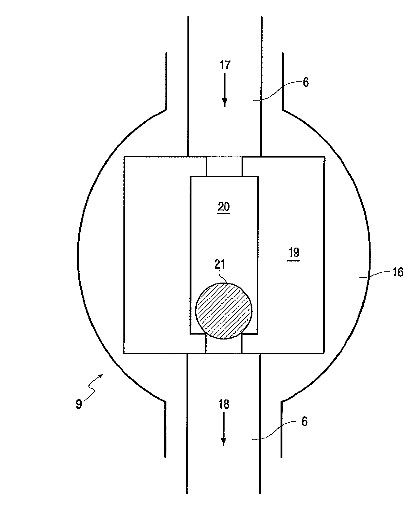
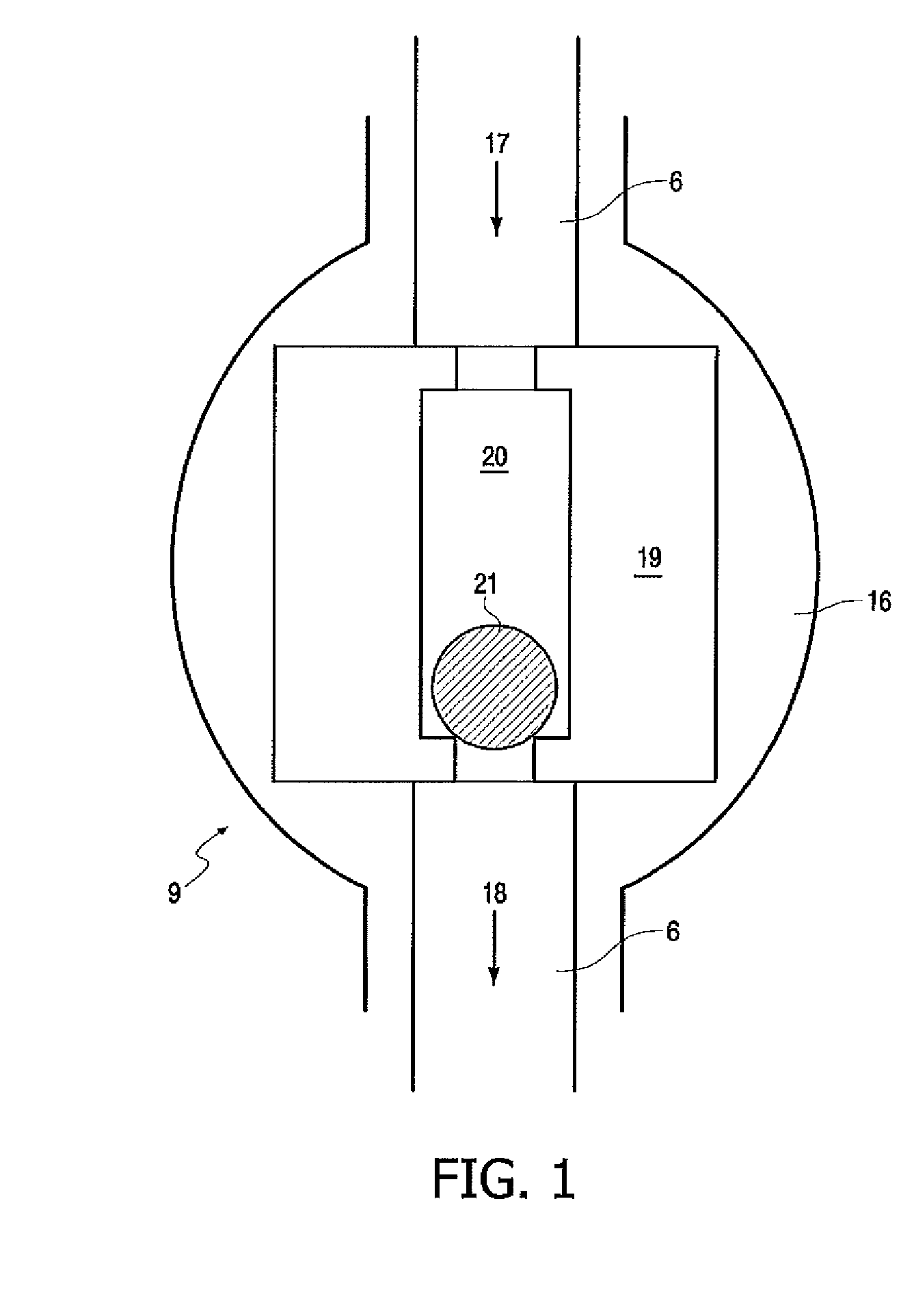
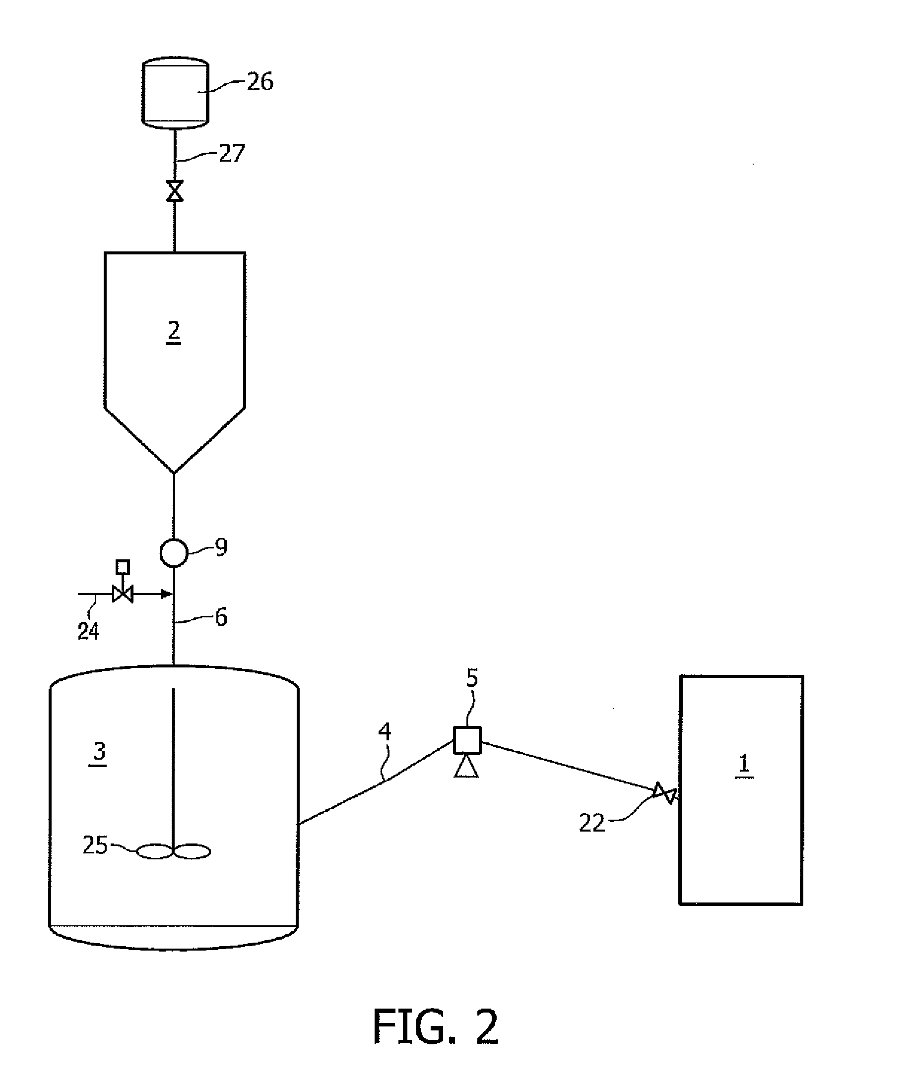
[0024]In one aspect, the present invention relates to a method for metering a catalyst slurry comprising the steps of:[0025]feeding said catalyst slurry to a catalyst metering device wherein said metering device determines an amount of catalyst slurry to be dispensed, and[0026]dispensing said metered catalyst slurry, wherein said catalyst metering device comprises a body, having an inlet and an outlet, comprising a rotatable catalyst metering valve, said valve comprising a catalyst metering chamber operably connected to said inlet and outlet, and a piston arranged within the chamber, characterized in that the rotatable catalyst metering valve is formed of an iron-based alloy steel hardened to a Rockwell hardness C of at least 60. In an embodiment said piston is a ball shaped piston.

[0027]In another aspect, the invention relates to a catalyst metering device comprising a body, having an inlet and an outlet, comprising a rotatable metering valve provided within the body, said valve co...


PUM

PropertyMeasurementUnit
Rockwell hardnessaaaaaaaaaa

Abstract

The invention relates to a catalyst metering device with a valve formed of an iron-based alloy steel hardened to a Rockwell hardness C of at least 60. The device can be used for metering of a catalyst for an ethylene polymerization reaction. The invention further relates to ethylene polymerization wherein the catalyst is metered in a catalyst metering device with a iron-based alloy steel hardened valve, as well as to a ethylene polymerization reactor comprising such a catalyst metering device.

Description

CROSS-REFERENCE TO RELATED APPLICATIONS[0001]This application claims the benefit of PCT / EP2011 / 063133, filed Jul. 29, 2011, which claims priority from EP 10171371.1, filed Jul. 30, 2010.TECHNICAL FIELD OF THE INVENTION[0002]The present invention relates to a catalyst metering device and a method for metering a catalyst slurry. This invention can advantageously be used in chemical manufacturing, specifically in the production of polyethylene (PE).BACKGROUND OF THE INVENTION[0003]Polyethylene (PE) is synthesized by polymerizing ethylene (CH2═CH2) monomers. Because it is cheap, safe, stable to most environments and easy to be processed polyethylene polymers are useful in many applications. According to the properties polyethylene can be classified into several types, such as but not limited to LDPE (Low Density Polyethylene), LLDPE (Linear Low Density Polyethylene), and HDPE (High Density Polyethylene). Each type of polyethylene has different properties and characteristics.[0004]Ethyle...

Claims


Application Information

Patent Timeline
Patent Type & Authority Patents(United States)
IPC IPC(8): E03B1/00C08F210/00C08F4/24C08F4/00C08F4/44C08F2/00
CPCB01J8/0015B01J2204/002B01J2208/00752B01J8/001F17D3/00Y10T137/0318B01J4/02B01J8/00B01J19/18F16K25/00
Inventor DEWACHTER, DAANBEKAERT, DANIEL
Owner TOTAL RES & TECH FELUY
Learn More