[0017]An object of the present invention is to provide a
remote control actuator of a type having a high accuracy in attitude alteration, in which the attitude of the tool coupled to the tip of the elongated pipe section can be changed by remote control and in which a spindle guide section as the pipe section can be altered in its attitude even if in a curved condition.
[0019]According to the above described construction, as a result of rotation of the tool fitted to the distal end member,
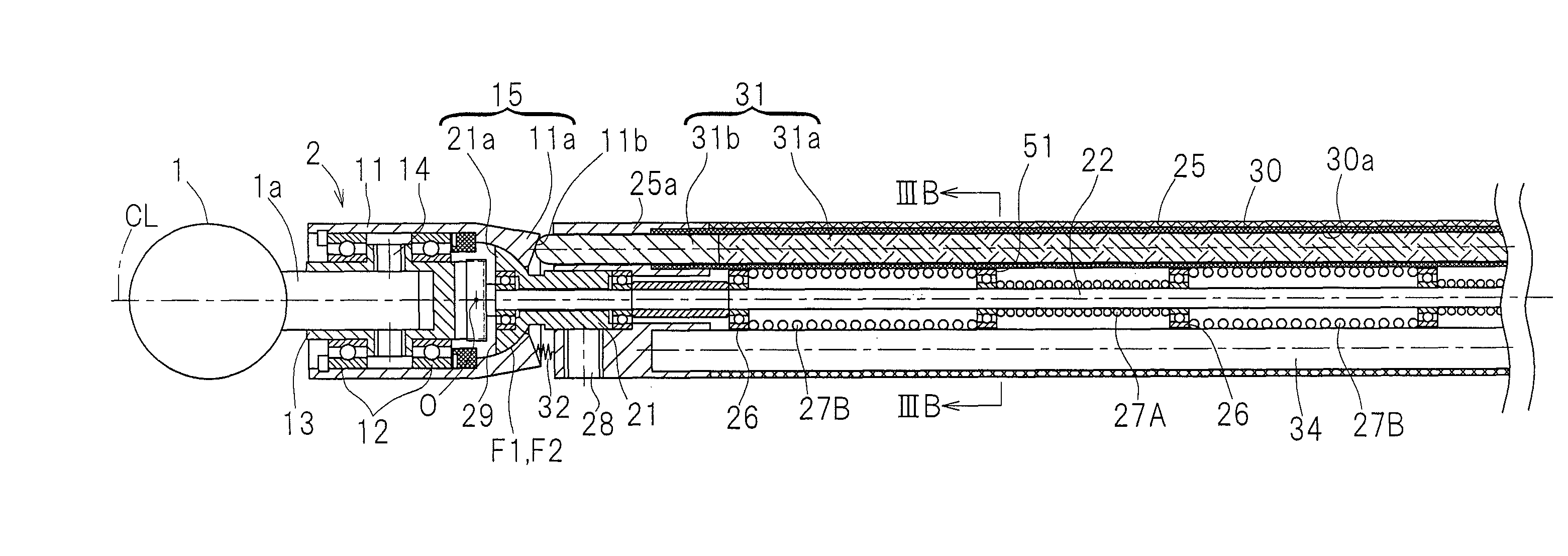
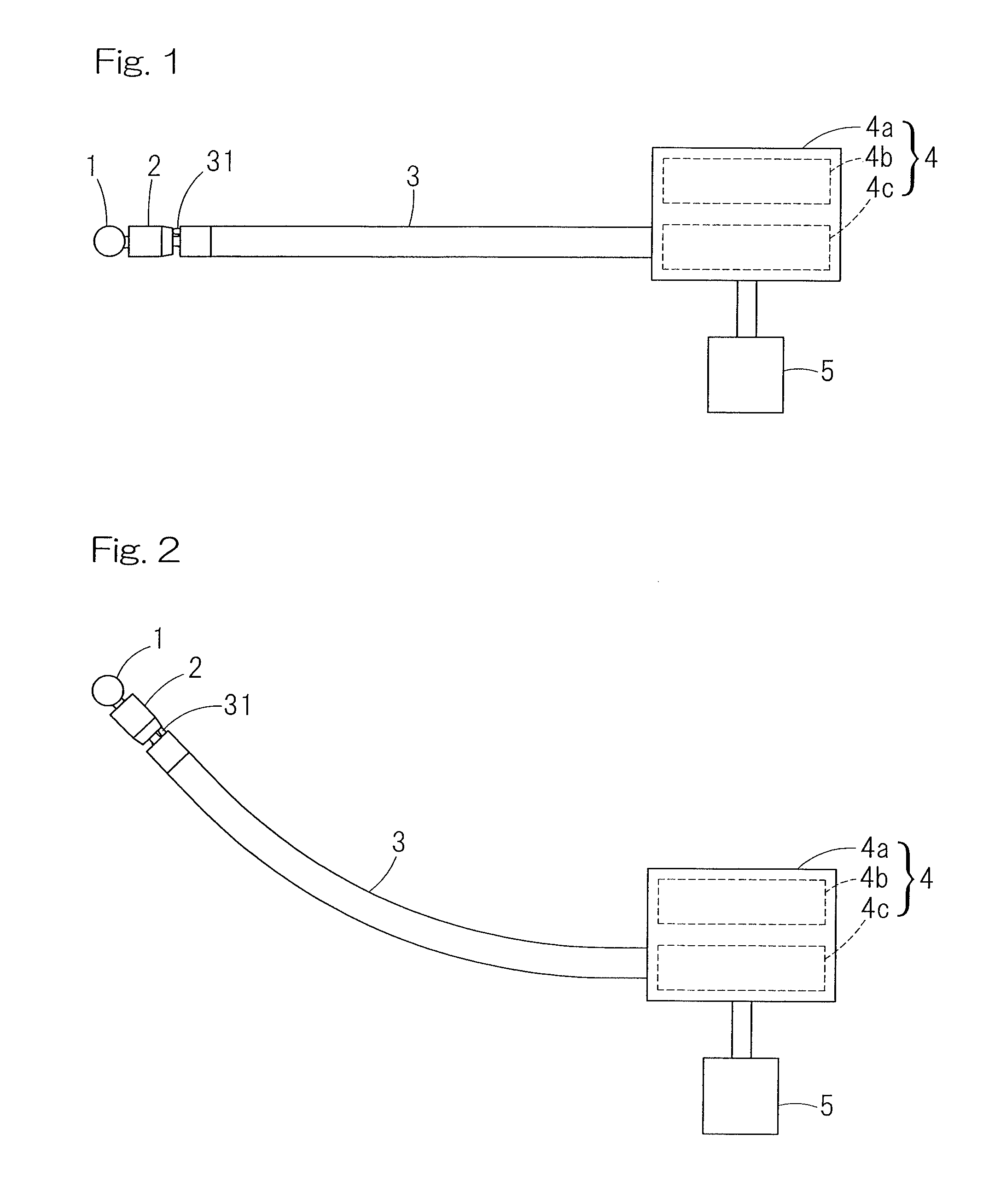
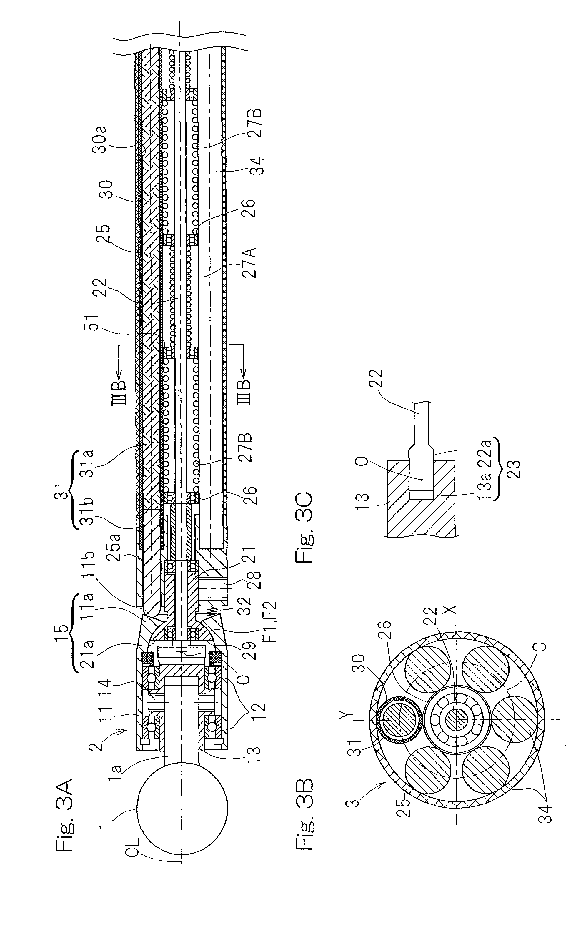
cutting of the bone or the like takes place. In such case, when the attitude altering member is selectively advanced and retracted one at a time by the attitude altering drive source, the tip end of the attitude altering member works on the distal end member to allow the attitude of the distal end member, fitted to the tip end of the spindle guide section through the distal end member connecting unit for alteration in attitude, to alter. The attitude altering drive source is provided at a position distant from the distal end member and the alteration of the attitude of the distal end member is carried out by remote control. Since the attitude altering member is passed through the guide hole, the attitude altering member can work on the distal end member properly at all time without being displaced in a direction transverse to the longitudinal direction thereof, and the operation to alter the attitude of the distal end member takes place accurately. Also, since the attitude altering member is flexible, the attitude altering operation takes place assuredly even when the spindle guide section is of a type having a curved portion.
[0020]The attitude of the distal end member can be estimated from the advanced or retracted position of the attitude altering member detected by the
position detector. If the attitude of the distal end member is ascertained, the
tip position of the tool is also ascertained and as a result, the processing with the tool can be accomplished accurately. Since the
position detector is provided at
a site separate from the attitude altering drive source, for example, the attitude altering member or the force transmitting member between the attitude altering drive source and the attitude altering member so that the advanced or retracted position of the attitude altering member can be detected at a position near to the attitude altering member, the detecting accuracy is high. By way of example, where the advanced or retracted position of the attitude altering member is to be estimated from the amount of activation of the attitude altering drive source, deformation or rattling motion of the force transmitting member between the attitude altering drive source and the attitude altering member appears as an error. However, detection at the position near to the attitude altering member is effective to increase the detecting accuracy with the error minimized.
[0021]In the present invention, the use may be made of a force increasing and transmitting mechanism within the drive
unit housing, which mechanism is comprised of a lever mechanism for increasing and transmitting to the attitude altering member, an output of a
direct acting member, which is selectively advanced or retracted by the attitude altering drive source in a linear direction. In such case, with a lever of the force increasing and transmitting mechanism used as the transmitting member, the position
detector may include a displacement amount measuring unit for measuring the amount of displacement of the lever and a displacement amount estimator for estimating the advanced or retracted position of the attitude altering member from a measured value of the displacement amount measuring unit. The use of the force increasing and transmitting mechanism is effective to increase an output of the attitude altering drive source and, therefore, the attitude altering drive source can be made compact. In case of use of the force increasing and transmitting mechanism, if the position
detector is of a structure including the displacement amount measuring unit and the displacement amount estimator, the amount of displacement of the lever of the force increasing and transmitting mechanism, which is the force transmitting member between the attitude altering drive source and the attitude altering member, is measured by the displacement amount measuring unit and, from the measured value thereof, the displacement amount estimator can estimate the advanced or retracted position of the attitude altering member.
[0024]In the present invention, the position
detector may include an advanced or retracted position measuring unit for measuring the advanced or retracted position of one end of the attitude altering member adjacent the drive
unit housing, and an advanced or retracted position estimator for estimating the advanced or retracted position of the attitude altering member from a measured value of the advanced or retracted position measuring unit. According to this construction, the advanced or retracted position of one end of the attitude altering member adjacent the drive
unit housing is measured with the advanced or retracted position measuring unit and, from the measured value thereof, the displacement amount estimator estimates the advanced or retracted position of the attitude altering member. Since the advanced or retracted position measuring unit detects directly the advanced or retracted position of that end of the attitude altering member, deformation or rattling motion of the force transmitting member between the attitude altering drive source and the attitude altering member does not appear as an error and therefore, the detecting accuracy is high.
[0027]In the present invention, the attitude altering drive source is a
rotary actuator provided outside the drive unit housing, in which case the use may be made of a rotation / advance or retraction converting and transmitting mechanism that is accommodated within the drive unit housing and is operable to convert the rotation of the attitude altering drive source into the advancing or retracting motion in the linear direction and then to transmit it to the attitude altering member. If the attitude altering drive source is employed in the form of the
rotary actuator, even in case of the provision of the attitude altering drive source at a location outside the drive unit housing, the rotation of the attitude altering drive source can easily be transmitted to the rotation / advance or retraction converting and transmitting mechanism. If the attitude altering drive source is provided outside the drive unit housing, the drive unit housing can be made compact. For this reason, the handleability at the time the remote controlled actuator is operated with the drive unit housing carried by an operator can be increased.


