
Converter lifetime improvement method for doubly fed induction generator

a technology of induction generator and conversion converter, which is applied in the direction of electric generator control, pulse technique, instruments, etc., can solve the problems of increasing transistor failure rate, increasing mechanical stress, and techniques that have not been able to account for the increase of stress

Active Publication Date: 2014-05-27
ROCKWELL AUTOMATION TECH
View PDF9 Cites 4 Cited by
  • Summary
  • Abstract
  • Description
  • Claims
  • Application Information

AI Technical Summary

Benefits of technology

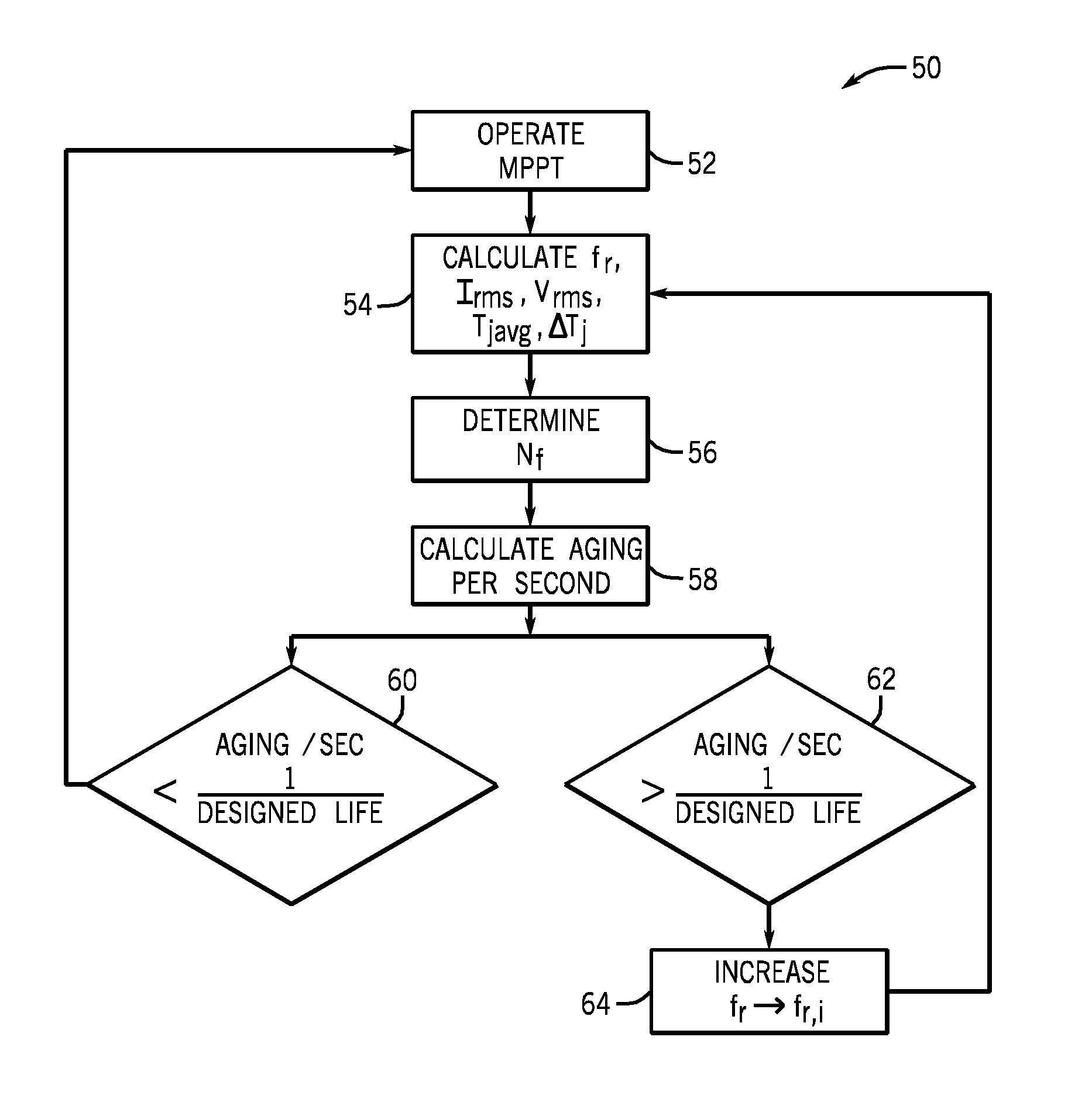
The present invention provides a transistor protection mechanism configuration to address high junction temperature variation and stress on the bond wires. The invention also includes methods to estimate the expected junction temperature variation and other associated parameters, such as number of cycles to failure and aging per second of the converter. The technical effects of the invention include reducing the operating frequency of a converter and improving its reliability and durability.

Problems solved by technology

Higher transistor switching speeds may tend, however, to increase the junction temperature of the transistors, which may result in more mechanical stress and increased rates of transistor failure over time.
However, these techniques have failed to account for the increased stresses that tend to occur under start-up conditions or low-speed conditions, wherein the transistors tend to experience high current at low output frequency.
Such low frequency conditions may contribute to electrical failures of the converter.

Method used


Image

  • Converter lifetime improvement method for doubly fed induction generator
  • Converter lifetime improvement method for doubly fed induction generator
  • Converter lifetime improvement method for doubly fed induction generator

Examples


Embodiment Construction

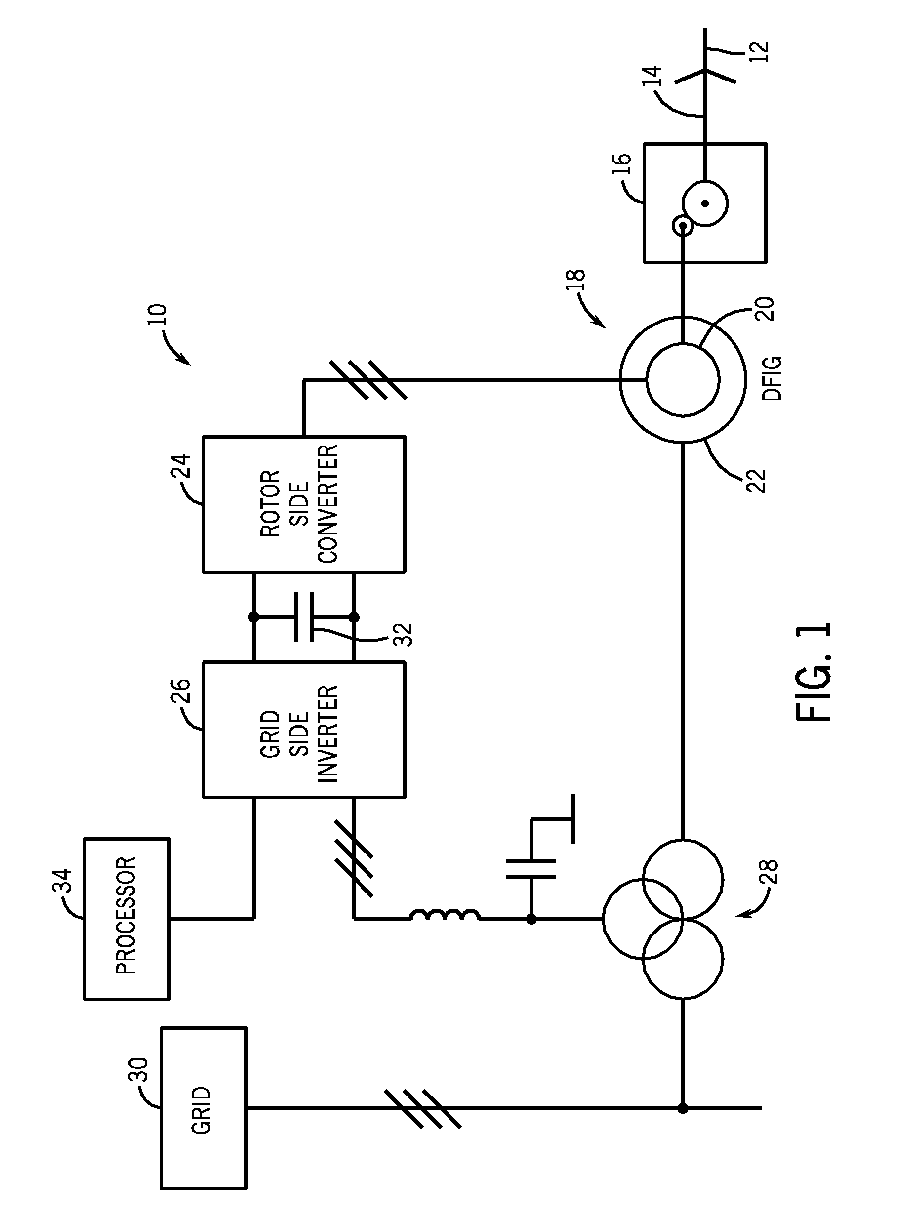
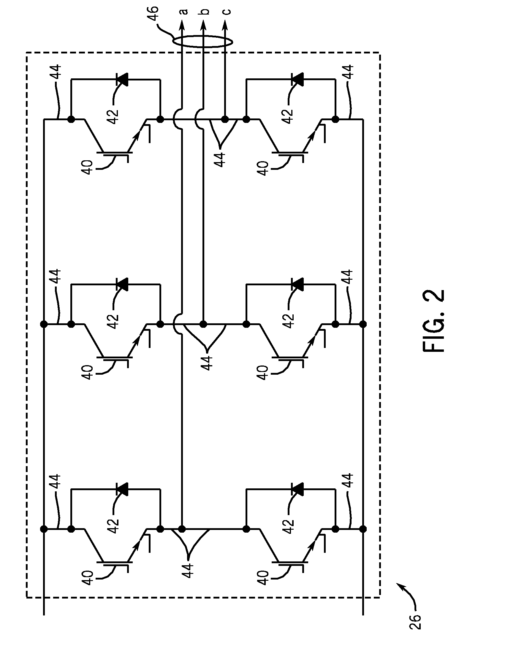
[0012]Embodiments of the present invention relate to reducing the mechanical stress on solid state switching devices, such as IGBTs due to large temperature variations of the junction. Large junction temperature variations may contribute to particularly high levels of mechanical stress, because the different expansion rates of the various materials inside the transistor package may lead to wire crack growth in wire bonds and similar contacts. Therefore, reducing junction temperature variations may result in a longer lasting converter module. In embodiments of the present invention, adverse affects of junction temperature variation is reduced by controlling the operating frequency of the converter module. Because the highest junction temperature variations tend to occur during operating conditions (e.g., start-up or low-frequency, high-current conditions), an aging parameter of the converter may be monitored, and the operating frequency may be increased when the aging parameter excee...


PUM


Abstract

The present techniques include methods and systems for operating converter to maintain a lifespan of the converter. In some embodiments, the operating frequency of the converter may be increased such that stress may be reduced on the bond wires of the converter. More specifically, embodiments involve calculating the aging parameters for certain operating conditions of the converter operating in a maximum power point tracking (MPPT) mode and determining whether the MPPT operation results in aging the converter to a point which reduces the converter lifespan below a desired lifespan. If the MPPT operation reduces the converter lifespan below the desired lifespan, the frequency of the converter may be increased such that the converter may be controlled to operate at a percentage of MPPT. Thus, in some embodiments, power output may be optimized with respect to maintaining a desired lifespan of the converter.

Description

BACKGROUND[0001]The invention relates generally to the field of electrical power converters and inverters. More particularly, the invention relates to techniques for preventing or forestalling failure of motor drive circuitry due to overheating.[0002]Power inverters and converters typically employ power modules to create a desired output current waveform, which is used to power various devices, such as motors and other equipment. The frequency and amplitude of the output current waveform may affect the operation of the device such as by changing the speed or torque of a motor, for example. Some power modules create the desired output current waveform through pulse width modulation, wherein power semiconductor switches such as insulated gate bipolar transistors (IGBTs) are caused to switch rapidly on and off in a particular sequence so as to create an approximately sinusoidal output current waveform. Furthermore, high transistor switching speeds tend to produce a smoother, more ideal...

Claims


Application Information

Patent Timeline
Patent Type & Authority Patents(United States)
IPC IPC(8): H02P9/04G01B3/52
CPCH02M1/32H02M7/537H02P9/007G05F1/67G01B3/52
Inventor WEI, LIXIANGKERKMAN, RUSSEL J.LUKASZEWSKI, RICHARD A.LU, HAIHUIYUAN, ZHENHUAN
Owner ROCKWELL AUTOMATION TECH
Learn More