
Synchronous motor control device for controlling synchronous motor to carry out power regenerative operation and stop synchronous motor at the time of power failure

a technology of synchronous motor and control device, which is applied in the direction of motor/generator/converter stopper, dynamo-electric converter control, dynamo-electric gear control, etc., can solve the problems of regenerative energy increase, over-voltage alarm, and over-voltage alarm, so as to avoid over-voltage, stop the synchronous motor both quickly and safely, and avoid the effect of over-voltag

Active Publication Date: 2014-05-06
FANUC LTD
View PDF18 Cites 2 Cited by
  • Summary
  • Abstract
  • Description
  • Claims
  • Application Information

AI Technical Summary

Benefits of technology

The present invention provides a synchronous motor control device that can prevent overvoltage across a DC link part without affecting the motor's cost and operating efficiency. This device also ensures safe and quick stop of the motor in case of an alternating-current power source failure, without issuing an over-voltage alarm. The device achieves this by setting the second direction current command value and the second power command value so that the motor generates no regenerative power when the alternating-current power source fails.

Problems solved by technology

In the case where such a power regenerative operation is carried out, it is not possible to return regenerative energy, which is generated during speed reduction of the motor, to the alternating-current power source side when the alternating-current power source fails, and therefore, an over-voltage (anomalous voltage) of a DC link part, which is connected in parallel to an inverter configured to supply alternating-current power to the motor, occurs.
However, in the case where a regenerative resistor or dynamic brake is provided in a motor control device, it is necessary to increase the resistance of the regenerative resistor or the capacity of the dynamic brake as the output of the motor increases, and therefore, there is such a disadvantage that the cost of the motor control device increases as the resistance of the regenerative resistor or the capacity of the dynamic brake increases.
However, in the case where a synchronous motor is controlled so as to carry out the power regenerative operation, the q-axis current contributes to generation of a torque, and therefore, if the value of the d-axis current of the synchronous motor is suppressed and the value of the q-axis current of the synchronous motor is increased during the speed reduction of the synchronous motor when the alternating-current power source fails, the regenerative energy increases, and therefore, there is a possibility of the issuance of an over-voltage alarm due to an over-voltage at the DC link part, which is connected in parallel to the inverter configured to supply alternating-current power to the synchronous motor.
Further, in the case where the value of the d-axis current is set to a value larger than zero at the time of the driving of the synchronous motor except for the driving of the synchronous motor during the speed reduction of the synchronous motor when the alternating-current power source fails, power consumed by the synchronous motor increases and the operating efficiency of the synchronous motor reduces remarkably.

Method used

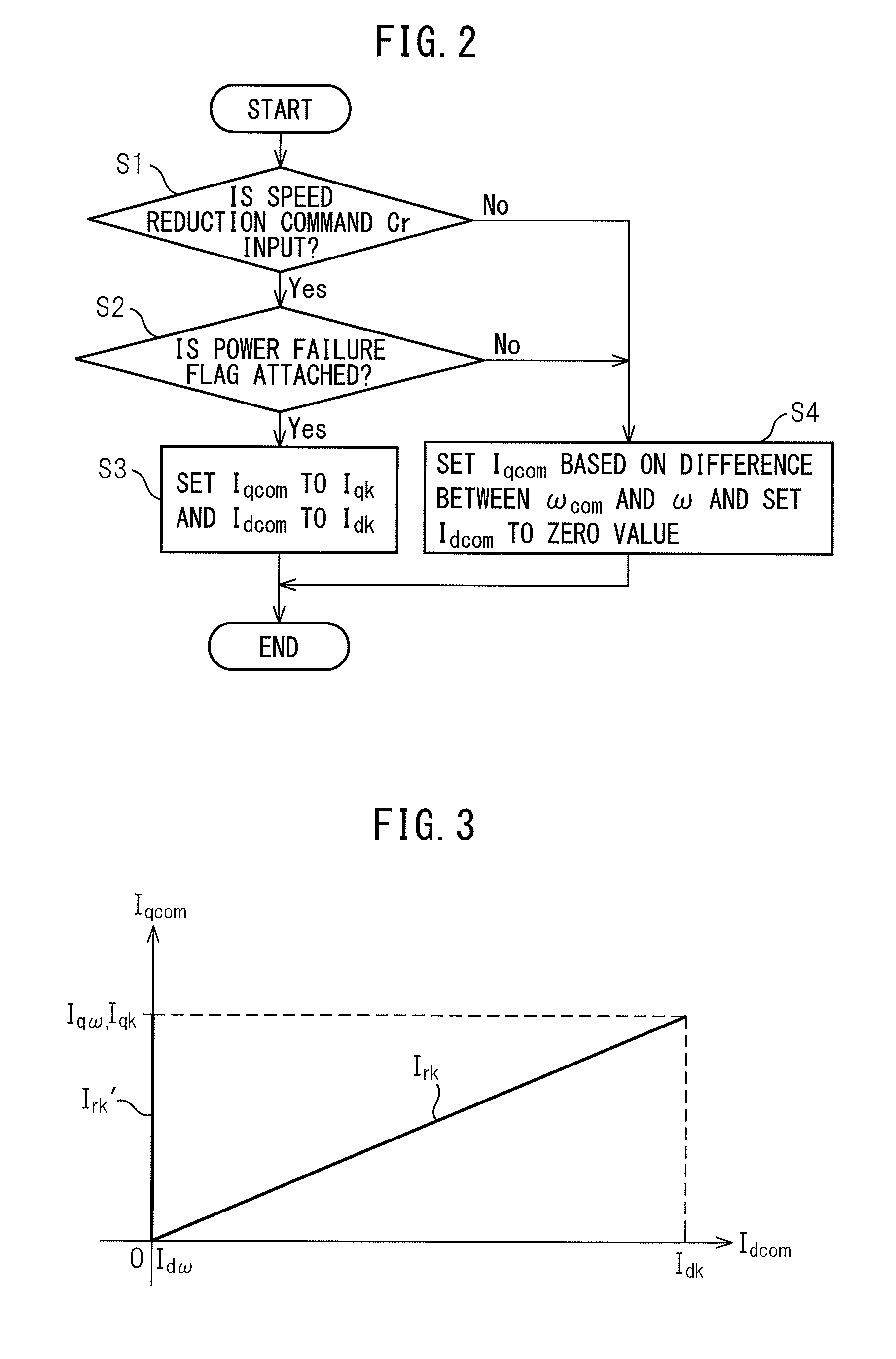

Image

  • Synchronous motor control device for controlling synchronous motor to carry out power regenerative operation and stop synchronous motor at the time of power failure
  • Synchronous motor control device for controlling synchronous motor to carry out power regenerative operation and stop synchronous motor at the time of power failure
  • Synchronous motor control device for controlling synchronous motor to carry out power regenerative operation and stop synchronous motor at the time of power failure

Examples


Embodiment Construction

[0020]Embodiments of the synchronous motor control device according to the present invention are explained with reference to the drawings.

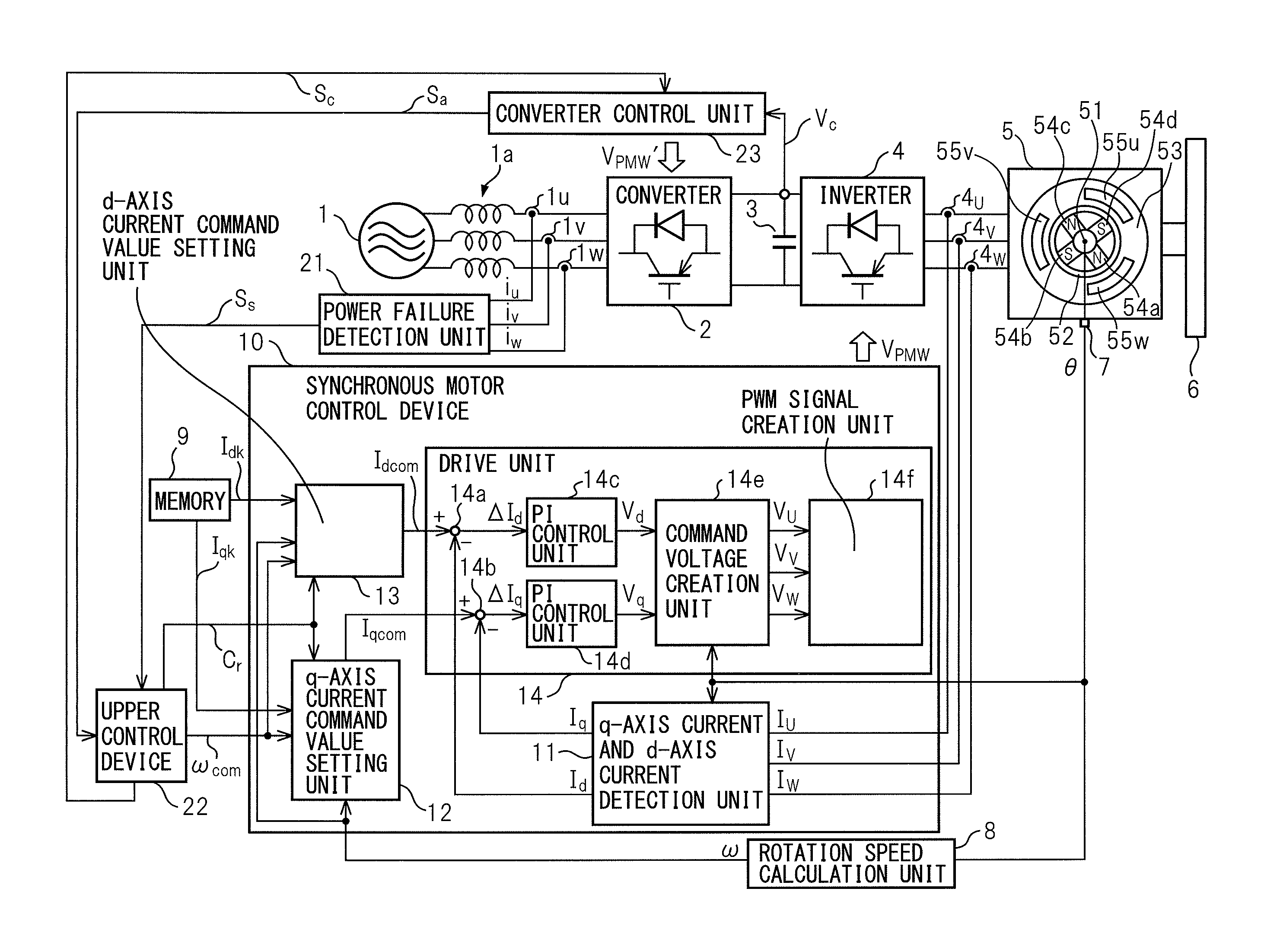
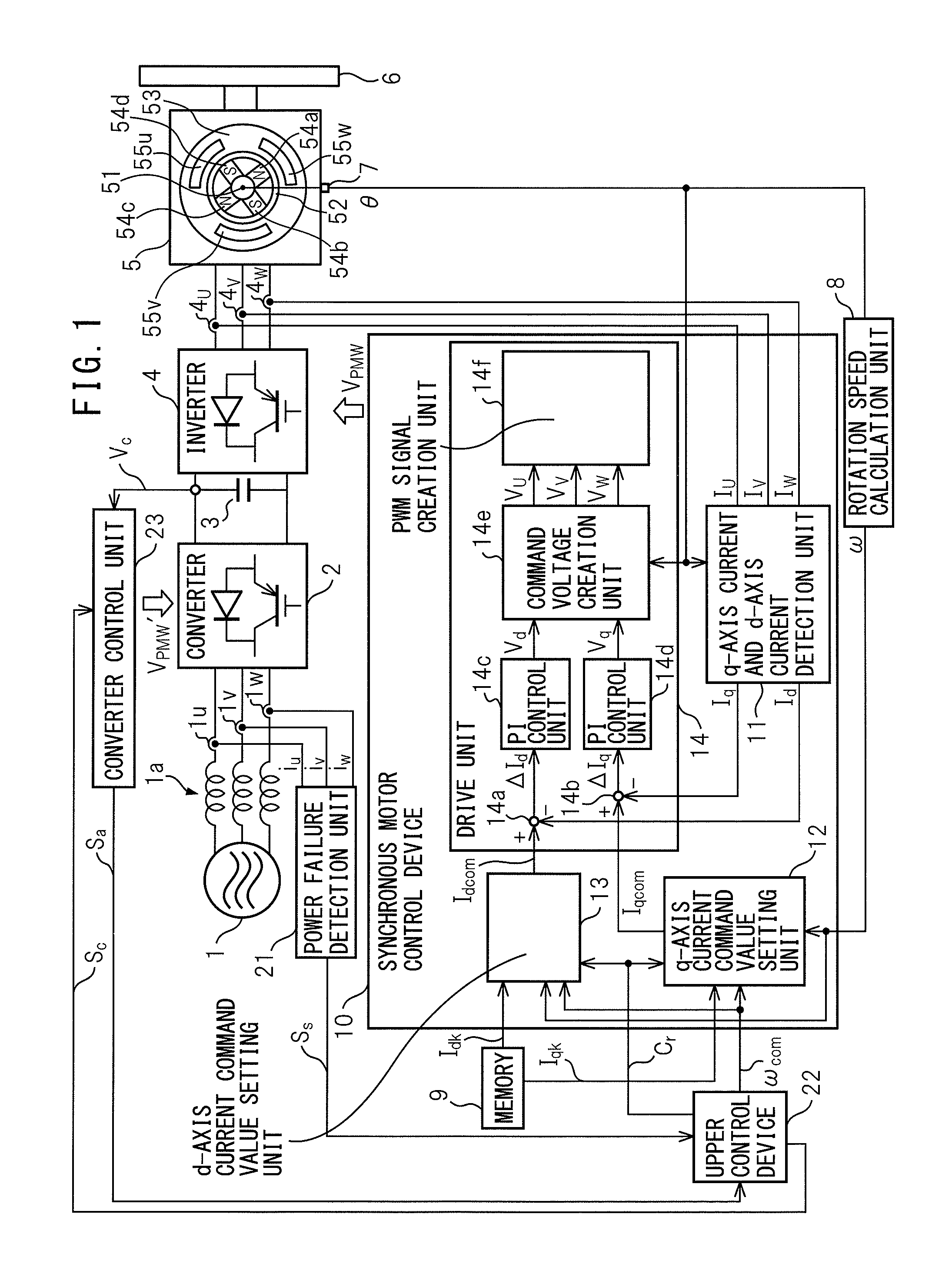
[0021]Referring to the drawings, FIG. 1 is a block diagram of a system having a synchronous motor control device of an embodiment of the present invention. The system shown in FIG. 1 has a three-phase alternating-current power source 1 as an alternating-current power source, a converter 2, a smoothing capacitor 3 as a DC link part, an inverter 4, a permanent magnet synchronous motor 5 as a synchronous motor, a driven object 6, a position detection unit 7, a rotation speed calculation unit 8, a memory 9, a synchronous motor control device 10, a power failure detection unit 21, an upper control device 22 and a converter control unit 23.

[0022]The converter 2 consists of a plurality (six, in the case of three-phase alternating current) of rectifier diodes and transistors connected in inverse parallel to the rectifier diodes, respectively, for example,...


PUM


Abstract

A second q-axis current command value, which is set by a q-axis current command value setting unit when an alternating-current power source fails at the time of driving of a synchronous motor, and a second d-axis current command value, which is set by a d-axis current command value setting unit when the alternating-current power source fails at the time of the driving of the synchronous motor, are set so that an absolute value of power per unit time of the synchronous motor is equal to loss per unit time of the synchronous motor.

Description

RELATED APPLICATIONS[0001]The present application is based on, and claims priority from, Japanese Application Number 2012-092269, filed Apr. 13, 2012, the disclosure of which is hereby incorporated by reference herein in its entirety.BACKGROUND OF THE INVENTION[0002]1. Field of the Invention[0003]The present invention relates to a synchronous motor control device for controlling a synchronous motor to carry out a power regenerative operation to return regenerative energy, which is generated during speed reduction of the synchronous motor, to the alternating-current power source side, and stop the synchronous motor when an alternating-current power source fails.[0004]2. Description of Related Art[0005]Conventionally, in order to handle regenerative energy, which is generated during speed reduction of a motor, a motor control device for controlling a motor to carry out power regenerative operation to return regenerative energy to the alternating-current power source side is used. In t...

Claims


Application Information

Patent Timeline
Patent Type & Authority Patents(United States)
IPC IPC(8): H02P21/00H02P3/18H02P21/22H02P21/36H02P23/16H02P27/04H02P27/08
CPCH02P21/0046H02P21/005H02P29/025H02P21/06H02P3/18
Inventor IWASHITA, YASUSUKEOGAWA, HAJIME
Owner FANUC LTD
Learn More