
Mining machine automation

Inactive Publication Date: 2014-04-08
STOLAR
View PDF8 Cites 9 Cited by
  • Summary
  • Abstract
  • Description
  • Claims
  • Application Information

AI Technical Summary

Benefits of technology

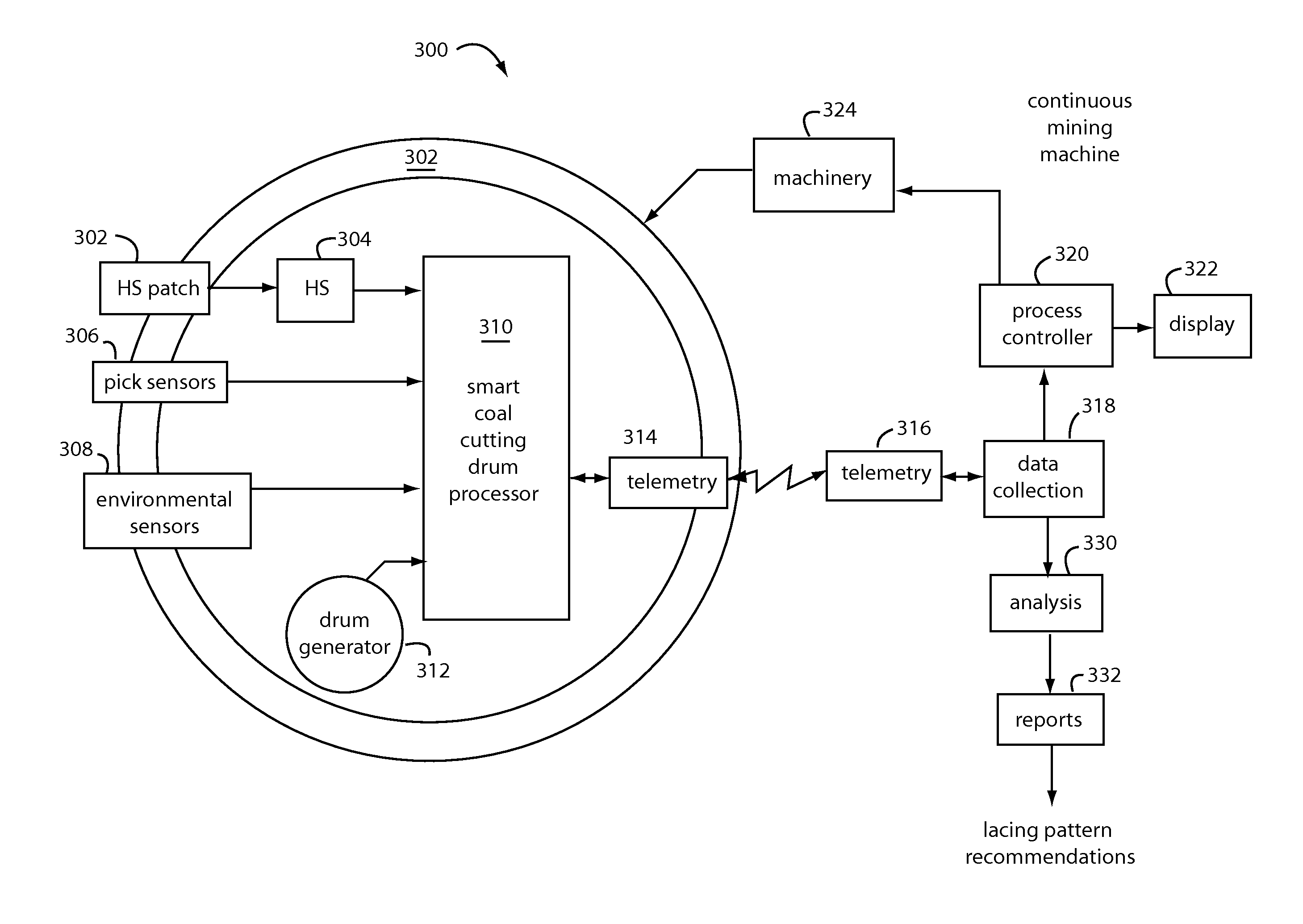
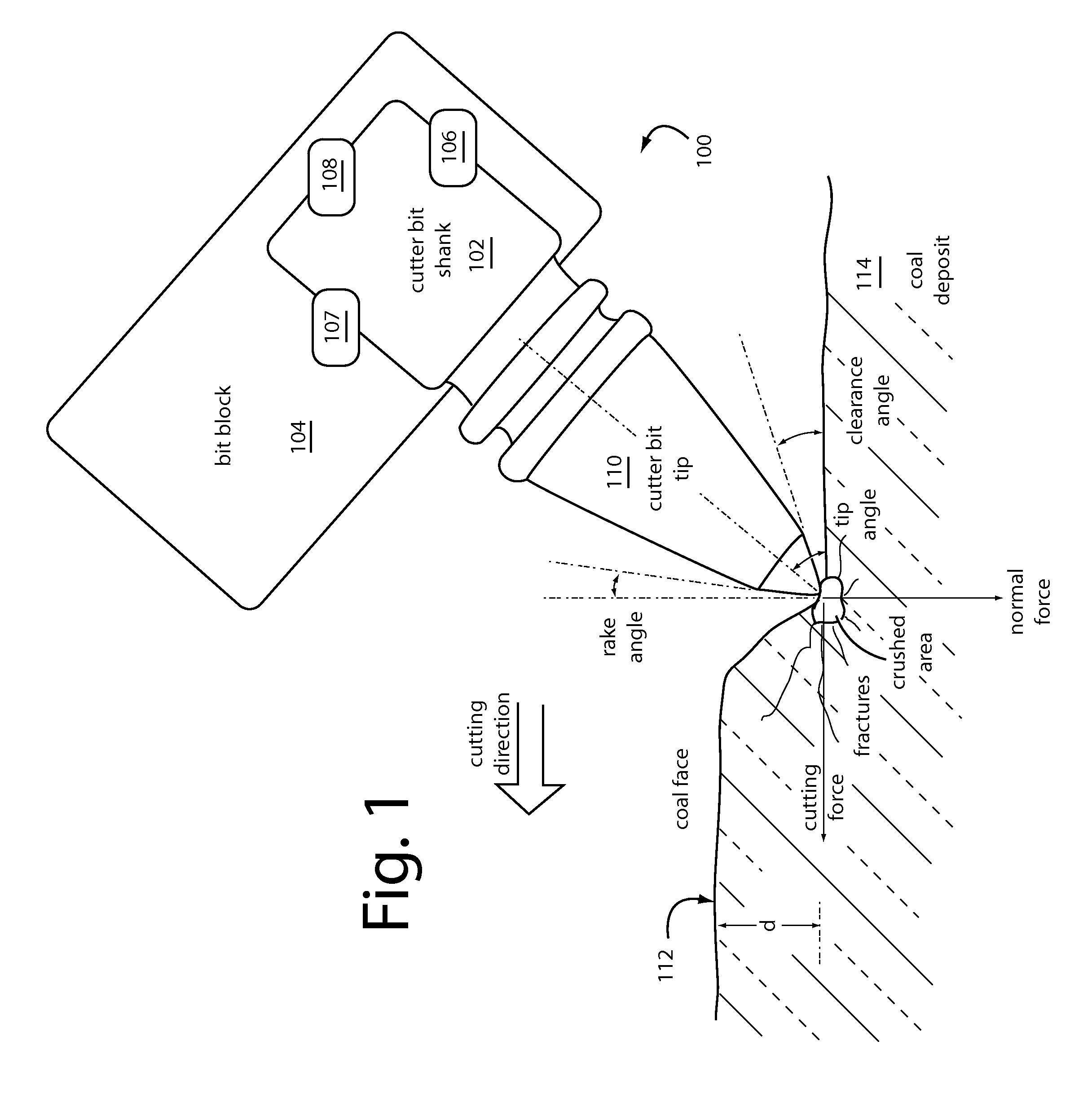
The present invention is an automated coal mining system that uses a continuous miner and longwall mining machine equipped with bit blocks and replaceable bit picks. The system includes strain gauges to measure the mechanical forces during coal cutting, and a resonant microwave patch antenna to measure the impedance of the coal face. The system can detect boundary layers of rock and work harder than necessary to cleave coal or make a better lacing pattern. The invention is designed to improve the safety and efficiency of coal mining operations by automating the cutting process and reducing hazards to operators. The patent describes the development of a smart coal cutting drum system and a continuous mining machine equipped with the system. The patent also explains how the system detects boundary layers of rock and works to improve coal quality.

Problems solved by technology

The coal fines and dust produced by continuous and longwall mining machines in underground coal operations is hazardous for a number of reasons.
Too much force will crush and pulverize the coal at the points of impact.
Subsequent strikes that do not follow the original fractures produced by the initial strikes wastes machine energy and reduces the flaking size.
Such can also increase the wear and tear experienced by the equipment.
Such significantly reduces the available explosive energies by absorbing the energy in the heat of fusion process by changing the phase state of water to gas.
The “last cut memory” horizon control algorithms are not useful in automated control of the shearer in undulating environment.
Of course, splay-deposits may restart contamination in mid-seam.
A serious environmental threat to the industry is the promulgation of rules declaring boiler fly ash toxic because of the re-oxidation of heavy metals in the combustion process.
The radar electromagnetic (EM) wave field components roundtrip travel time is less than two nanoseconds that creates a detection and interpretation problem for conventional GPR.

Method used


Image

  • Mining machine automation
  • Mining machine automation
  • Mining machine automation

Examples


Embodiment Construction

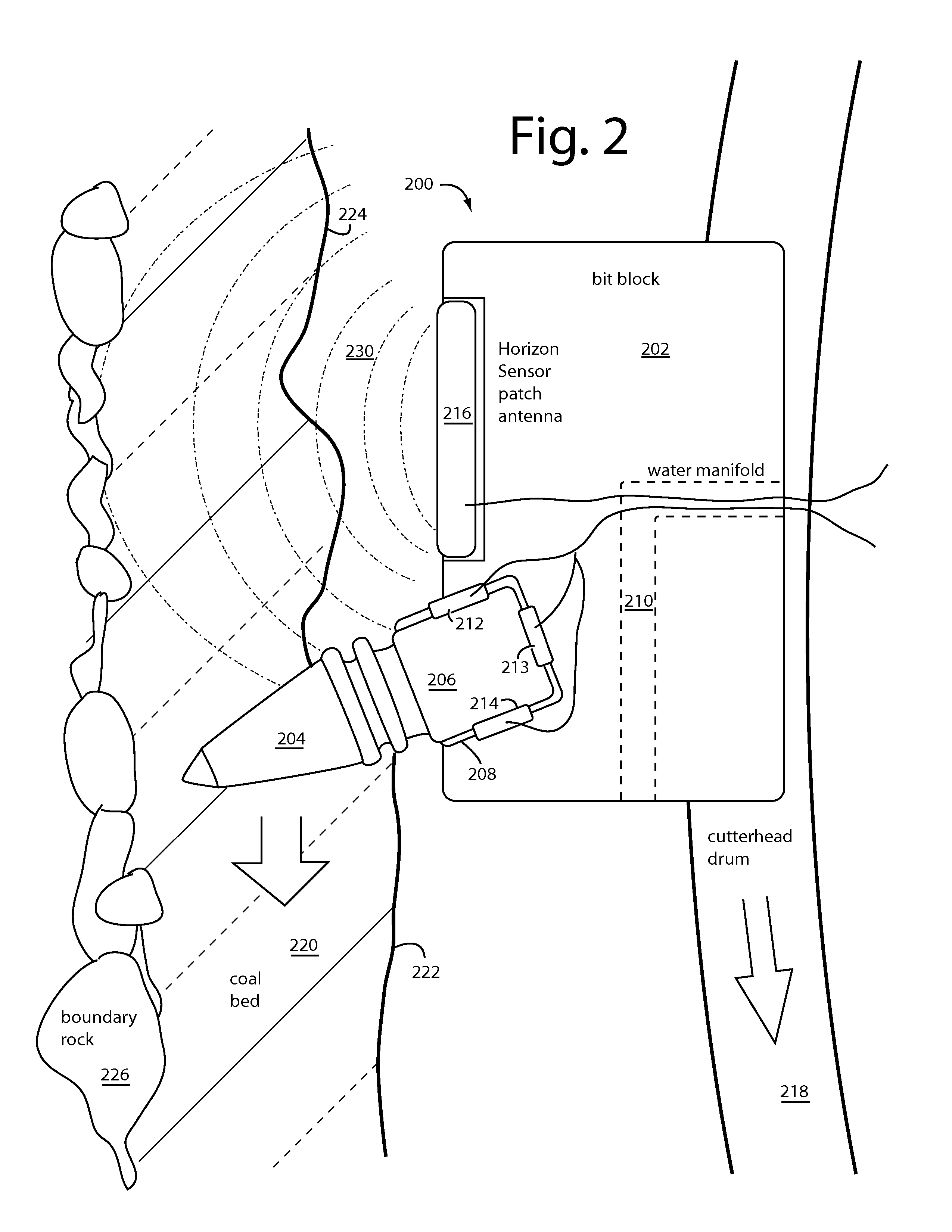
[0039]Embodiments of the present invention are an advance Stolar horizon sensing technology. A resonating microstrip patch antenna (RMPA) is integrated into a bit block following the pick receiver. Such location presses the RMPA into the coal cut, fractured, and wet coal layer. SCARE spatial suppression of the early-to-arrive EM field components with respect to the later arriving reflected field components enables advanced automation of coal cutting machines while increasing miner health and safety. For construction details on the spatial suppression, see our U.S. Pat. No. 7,656,342, issued Feb. 2, 2010, titled, DOUBLE-SIDEBAND SUPPRESSED-CARRIER RADAR TO NULL NEAR-FIELD REFLECTIONS FROM A FIRST INTERFACE BETWEEN MEDIA LAYERS. Such is incorporated herein by reference, in full.

[0040]Embodiments of the present invention have “rejection zones” tunable to the depths subject to clutter and / or unimportant dielectric variations. Dangerous and harmful objects will be deeper, in the layers u...


PUM


Abstract

An automated coal mining system outfits rotating cutterhead drums with bit blocks and replaceable bit picks according to a lacing pattern. A set of strain gauges are configured to measure the mechanical forces experienced by the bit picks during coal cutting. Measurements are taken that can be processed for indications that the replaceable bit picks have encountered a boundary layer of rock during coal cutting operations, or they are working harder than necessary to cleave coal, or that a better lacing pattern is possible. A resonant microwave patch antenna is mounted on a top surface shoulder of the bit blocks to take impedance measurements of the coal face. The impedance measurements are calibrated according to indications that the replaceable bit picks have encountered a boundary layer of rock. The rotating drum sensor data is wirelessly transmitted back to the machine for analysis and control purposes.

Description

RELATED APPLICATION[0001]This Application claims benefit of U.S. Provisional Patent Application Ser. 61 / 675,855, filed Jul. 26, 2012, and titled, HYDRAULIC DRILLSTRING SOUND GENERATOR; and, U.S. Provisional Patent Application Ser. 61 / 675,838, filed Jul. 26, 2012, and titled, SMART COAL CUTTING DRUM. Such are incorporated herein, in full, by reference, as is U.S. patent application Ser. No. 13 / 561,390, filed Jul. 30, 2012.BACKGROUND OF THE INVENTION[0002]1. Field of the Invention[0003]The present invention generally relates to automated coal mining, tools, equipment, and methods, and more particularly to using force measurements obtained from individual bit picks in bit blocks on continuous and longwall mining machine coal cutterhead drums to reduce the generation of coal cleaving fines, to automatically calibrate earth-penetrating radars, and to predict the best orientations, lacing patterns, and positions for replacement bit picks and cutterhead drums at a next service interval.[00...

Claims


Application Information

Patent Timeline
IPC IPC(8): E21C35/00
CPCE21C35/18E21C27/02E21C39/00E21C35/00
Inventor STOLARCZYK, LARRY, G.
Owner STOLAR
Learn More