
Method and system for automatic connection to a network

Active Publication Date: 2014-04-01
BRITISH TELECOMM PLC
View PDF26 Cites 15 Cited by
  • Summary
  • Abstract
  • Description
  • Claims
  • Application Information

AI Technical Summary

Benefits of technology

The patent text describes a method for improving the efficiency and performance of data communication by automatically selecting the best network access point for a communications terminal based on the user's location and the capabilities of the available network access points. The method involves establishing a first access channel with a network and receiving profile information identifying one or more further network node(s) from which the terminal can communicate. The method can also include detecting the presence of a second network node and using the profile information to automatically establish a new access channel with the second network node and communicate data thereover. The access data may include security information such as passwords or encryption keys required to establish new access channels with the network. The geographical location of the terminal can be determined using various methods such as WIMAX triangulation, Wi-Fi triangulation, cellular triangulation, Bluetooth access point triangulation, or IP address resolution. The technical effect of the invention is to optimize data transfer by automatically selecting the best network access point for a communications terminal based on its location and the capabilities of the available network access points.

Problems solved by technology

The manual selection process carried out by the user may pay little regard to the performance or cost associated with data transfer using a particular access point, through lack of familiarity with what is currently available, and its capabilities.
This means that data transfer is often effected via an access point which does not provide the most efficient or suitable means of data transfer to or from the network.

Method used


Image

  • Method and system for automatic connection to a network
  • Method and system for automatic connection to a network
  • Method and system for automatic connection to a network

Examples


Embodiment Construction

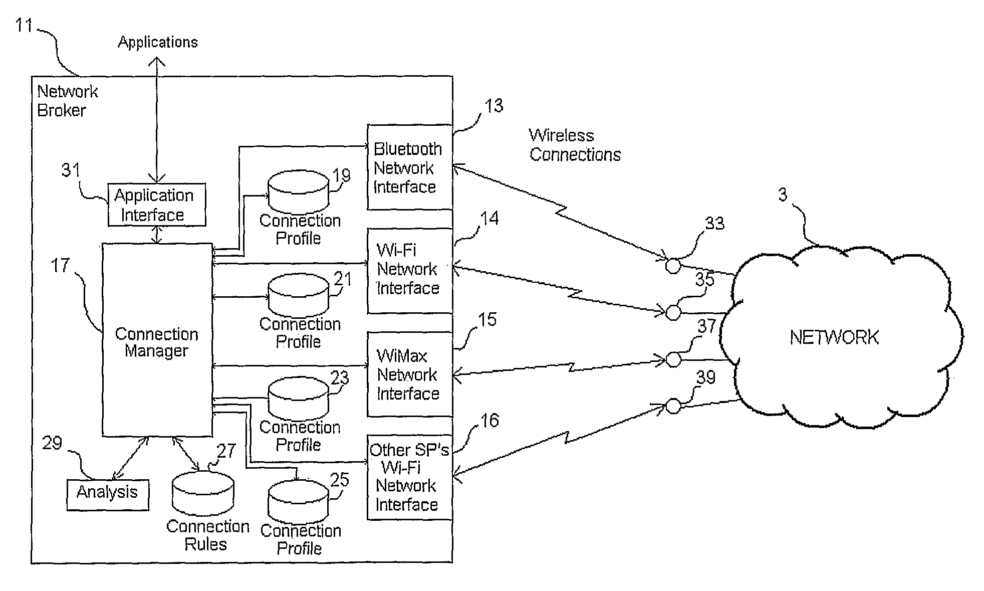
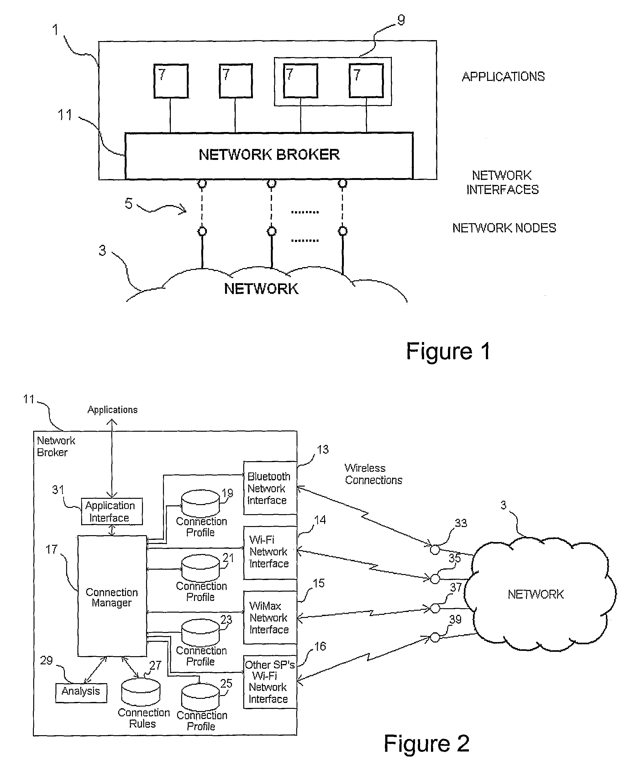
[0052]Referring to FIG. 1, a communications terminal 1 is shown connected to a network 3 by means of a plurality of data channels 5. The terminal 1, which may, for example, be a mobile telephone, personal digital assistant (PDA) or laptop computer, comprises a number of application programs 7 each of which is capable of sending and receiving data over the network 3 via one or more of the data channels 5. For example, a first application may be a Voice over Internet Protocol (VoIP) application providing a voice communications facility between the terminal 1 and one or more other terminals on the network 3. A second application may be an email application, and so on. As indicated in FIG. 1, multiple application programs 7 may be provided in a single client 9 providing a consistent application-level interface to remote network facilities.

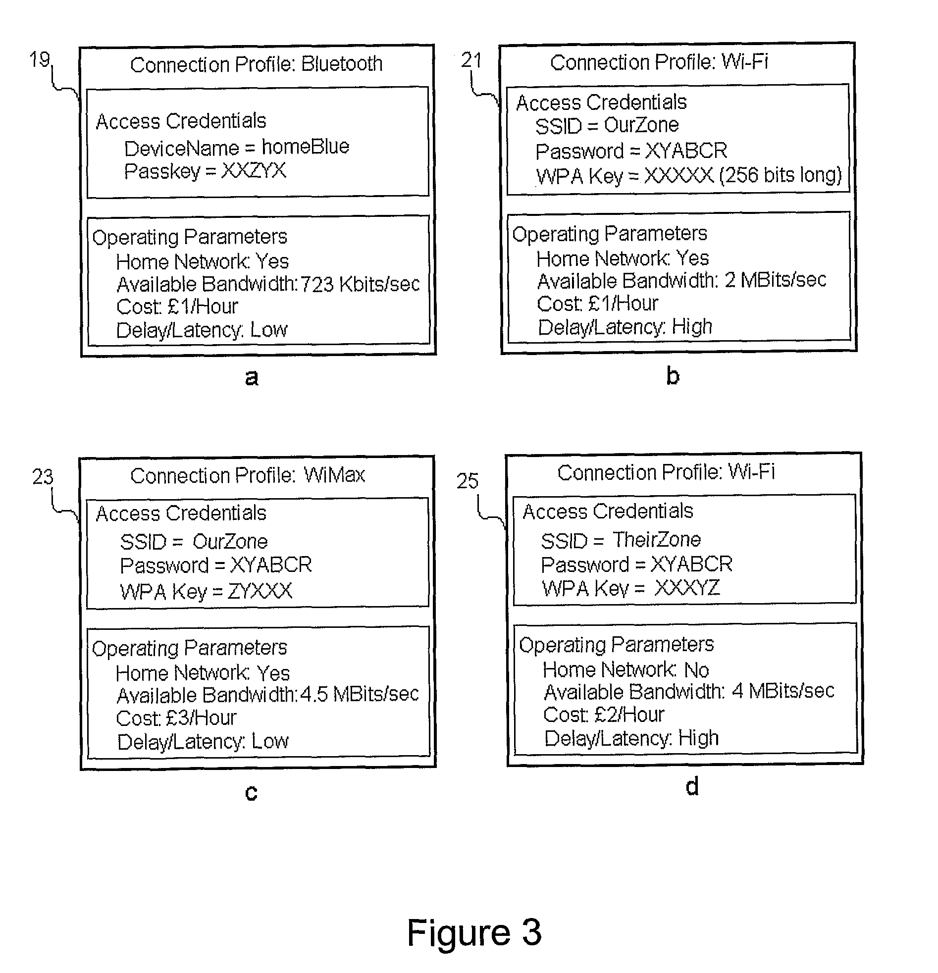
[0053]The terminal 1 comprises a plurality of different network interfaces. Each network interface is capable of connecting to the network 3 by establ...


PUM


Abstract

A processing terminal, for example a PDA or laptop, includes one or more application-layer programs and a network broker. The network broker exposes currently-available network resources, such as network access points in-range of the terminal, to the applications layer. The network broker is also arranged to automatically establish network connections via the or each network access point and to acquire operating parameters indicative of the status and / or performance of the connections. The available bandwidth of a connection is one example of an operating parameter. Data subsequently sent to, or transmitted from, the application-layer programs is communicated over a selected one or more of the established connections in accordance with predefined connection rules indicating which connection is / are to be selected in dependence on the operating parameters. Access credentials for enabling the terminal automatically to access a network via a different access point can also be provided using an existing connection.

Description

[0001]This application is the U.S. national phase of International Application No. PCT / GB2009 / 000121 filed 15 Jan. 2009, which designated the U.S. and claims priority to GB Application No. 0802003.4 filed 4 Feb. 2008; and GB Application No. 0805399.3 filed 25 Mar. 2008, the entire contents of each of which are hereby incorporated by reference.BACKGROUND AND SUMMARY[0002]The invention relates to data communications, and particularly to a method of operating a communications terminal, a method of providing access information to a communications terminal and apparatus for performing the methods.[0003]In order for communications terminals to communicate with a network, it is usual to first establish a connection between a network interface of the terminal and a network access point. In the case of the Internet, for example, a modem is used by the terminal to establish a connection with the server of an Internet Service Provider (ISP) via a telephone line, the resulting connection being ...

Claims


Application Information

Patent Timeline
IPC IPC(8): H04W4/00H04W4/029
CPCH04W64/003H04W88/06H04W4/028H04W48/12H04L12/5692H04L69/18H04W4/029
Inventor COLLINGRIGE, ROBERT
Owner BRITISH TELECOMM PLC
Learn More