
Current measurement in switched mode power supply

a power supply and switching mode technology, applied in the direction of instruments, electric devices, measurement using digital techniques, etc., can solve the problems of transients introducing current errors, varying offset errors, and challenging power supply requirements

Active Publication Date: 2014-03-18
TELEFON AB LM ERICSSON (PUBL)
View PDF5 Cites 9 Cited by
  • Summary
  • Abstract
  • Description
  • Claims
  • Application Information

AI Technical Summary

Benefits of technology

This approach improves measurement accuracy significantly, achieving results comparable to the best existing statistical methods after only 1 or 2 iterations, while being suitable for hardware implementation and parallel processing, thus enhancing current determination in SMPS.

Problems solved by technology

This puts new challenging requirements on the power supply, such as tighter voltage tolerance bands and the ability to provide increased current levels.
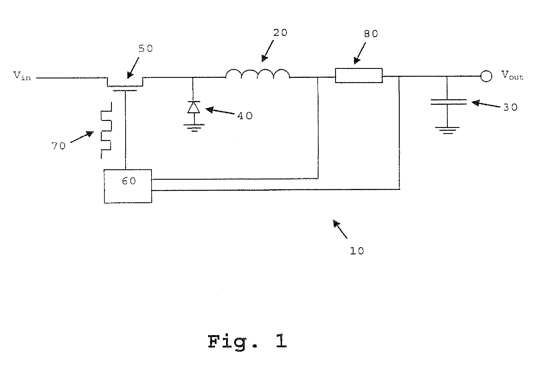
However, the switching of the transistor can cause transients which introduce errors in the current values measured shortly after a transition from an ON-period to the following OFF-period or from an OFF-period to the next ON-period.
However, this method introduces an offset error that varies with the blanking time and the duty cycle.
Hence, the accuracy and latency of this method is not very good.

Method used


Image

  • Current measurement in switched mode power supply
  • Current measurement in switched mode power supply
  • Current measurement in switched mode power supply

Examples


Embodiment Construction

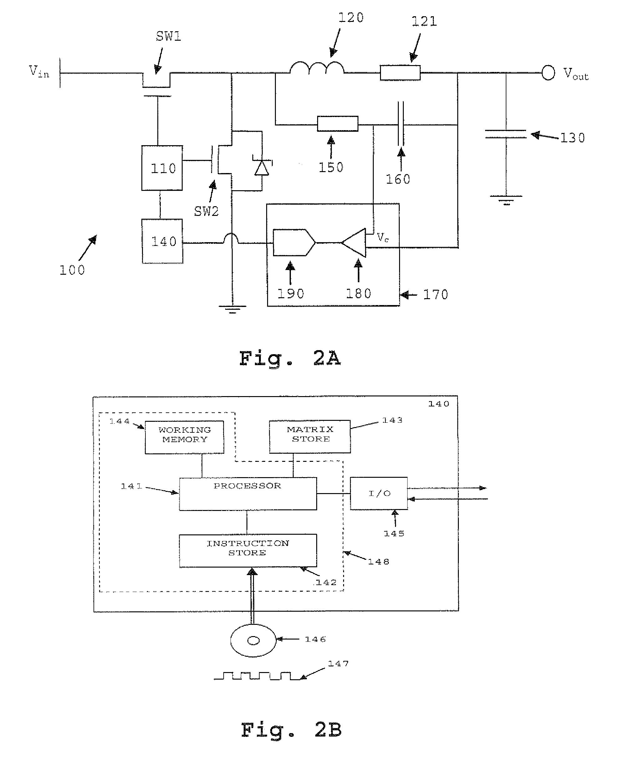
[0038]FIG. 2A is a schematic of a switched mode DC / DC power supply 100 according to a first embodiment of the present invention. The power supply includes transistors SW1 and SW2 which are preferably power MOSFETs. The switching of transistors SW1 and SW2 is controlled by a PWM controller 110. The PWM controller 110 is configured to apply voltage pulses preferably at a frequency in the range between 20 kHz and 1 MHz to the gates of transistors SW1 and SW2, and to vary the duty cycle of the switching in response to a feedback signal received from a signal processing unit 140. Alternatively, instead of the PWM controller 110 a frequency-modulating controller (not shown) can be used, which modulates the frequency at which pulses of a fixed duration are generated. The source terminal of transistor SW1 is connected to a DC voltage line at Vin while the source of transistor SW2 is connected to a reference point such as earth. The drain of each transistor is connected to an output filter, ...


PUM


Abstract

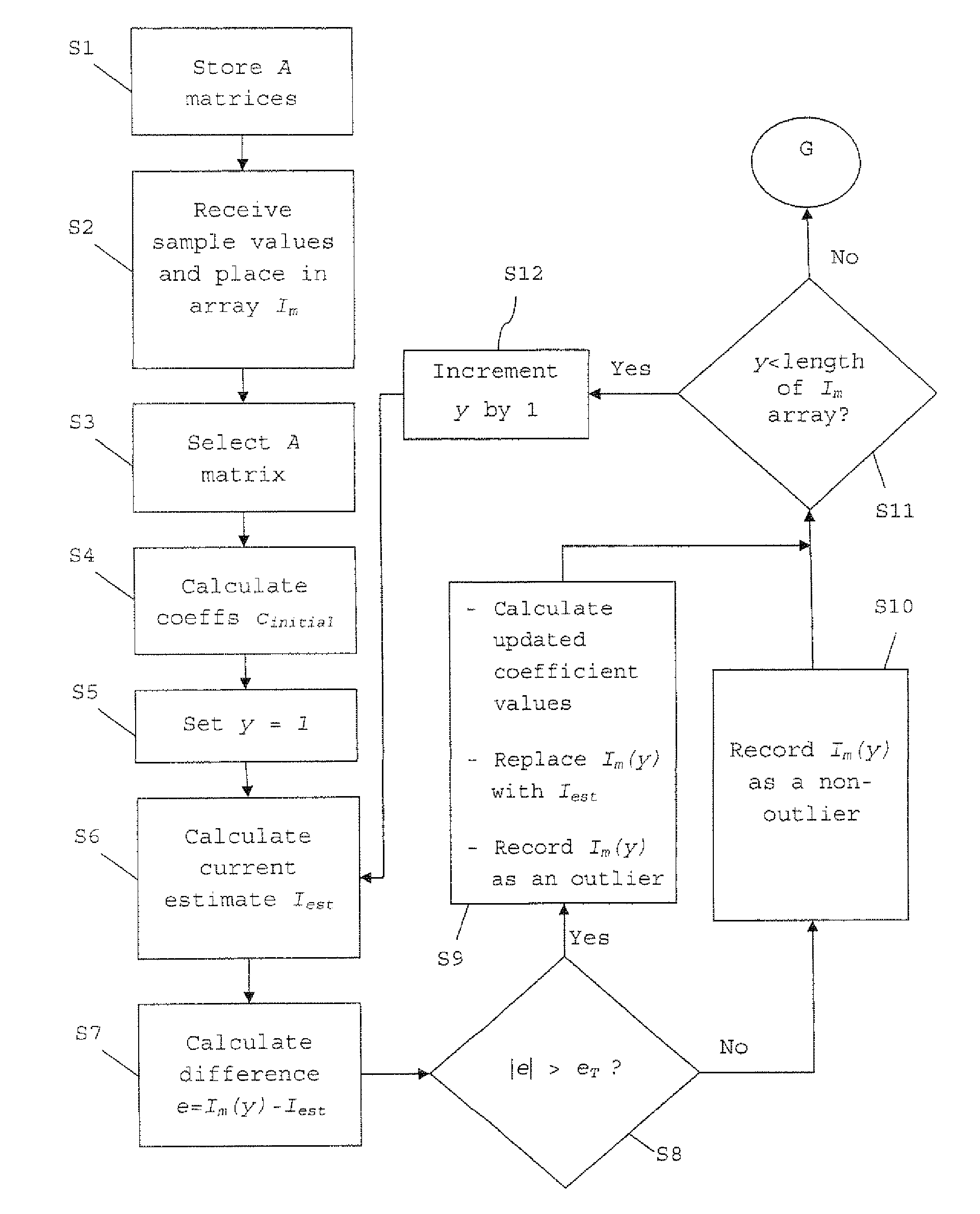
A method of determining a current in a switched mode power supply. The method comprises: storing values representing at least one pre-calculated matrix A; receiving measured current values; and using the stored values representing the matrix A and the received current values to calculate a respective initial value for each of the coefficients of the line and for each measured current value: calculating an estimated current using the equation of the line and the calculated initial values of the coefficients; determining a difference between the measured current value and the estimated current value to generate a difference value, and comparing the difference value against a threshold and, if the difference value is greater than the threshold, calculating updated values of the coefficients using stored values representing matrix A and difference value. A value for the current in the switched mode power supply is determined using the updated values of the coefficients

Description

TECHNICAL FIELD[0001]The present invention generally relates to the field of switched mode power supplies (sometimes referred to as switch mode supplies or switching mode power supplies) and more specifically to determination of a current in a switched mode power supply.BACKGROUND[0002]The switched mode power supply (SMPS) is a well-known type of power converter having a diverse range of applications by virtue of its small size and weight and high efficiency, for example in personal computers and portable electronic devices such as cell phones. An SMPS achieves these advantages by switching a switching element such as a power MOSFET at a high frequency (usually tens to hundreds of kHz), with the frequency or duty cycle of the switching being adjusted using a feedback signal to convert an input voltage to a desired output voltage. An SMPS may take the form of a rectifier (AC / DC converter), a DC / DC converter, a frequency changer (AC / AC) or an inverter (DC / AC).[0003]It is desirable to ...

Claims


Application Information

Patent Timeline
Patent Type & Authority Patents(United States)
IPC IPC(8): G06F19/00
CPCG01R19/25H02M2001/0009H02M3/156H02M1/0009
Inventor HOLMBERG, TORBJORNKARLSSON, MAGNUS
Owner TELEFON AB LM ERICSSON (PUBL)
Learn More