Ion implanter

a technology of implanters and ion beams, applied in the field of ion beams, can solve the problems of less desirable in view of the relationship with the disposed location of other apparatuses, and achieve the effect of reducing the emission of ion beams and reducing the expansion and contraction of ion beams

Inactive Publication Date: 2014-02-18
NISSIN ION EQUIP CO LTD
View PDF4 Cites 2 Cited by
  • Summary
  • Abstract
  • Description
  • Claims
  • Application Information

AI Technical Summary

Benefits of technology

[0012]Therefore, an object of the present invention is to provide an ion implanter capable of decreasing expansion or contraction of an ion beam in a long side direction in the case where a beam current density distribution of the ion beam having a substantially rectangular cross section in a long side direction is adjusted.
[0014]The electric field is generated in the short side direction of the ion beam when adjusting the beam current density distribution and the ion beam is locally deflected toward the substantially short side direction. Therefore, it is possible to significantly reduce expansion and contraction of the ion beam in the long side direction thereof which occurs in an electric field lens of the related art.
[0018]With the above configuration, since the respective electrodes configuring the electrode group is at the negative potential or at the ground potential, electrons contained in the ion beam or electrons floating in a transport path of the ion beam are not drawn to the respective electrodes, but are reflected from the electrode having the negative potential to the ion beam side. The electrons reflected to the ion beam side serve to suppress emission of the ion beam due to the space charge effect. Accordingly, it is possible to reduce the possibility that the ion beam is emitted by the space charge effect and thus collides with a wall surface of the vacuum chamber configuring the transport path of the ion beam.
[0020]With the above configuration, it is possible to eliminate neutral particles generated in the beam path. Further, since the potential of the respective power sources connected to the electrode group is collectively adjusted by the bias power source, it is possible to reduce the power consumption of the power source, as compared to the case where the power source connected to the respective electrodes configuring the electrode group is respectively adjusted to eliminate the neutral particles. In addition, since it is not necessary to install a plurality of power source having a high voltage source capacity, a cost can be decreased to that extent.
[0022]In the example utilizing the above-described bias power source, since the electrons are not drawn to the respective electrodes configuring the electrode group, it is possible to reduce the emission of the ion beam due to the space charge effect, in addition to the above-described effects.
[0023]In the case of adjusting the beam current density distribution in the long side direction of the ion beam having the substantially rectangular cross section by means of the electric field lens, it is possible to significantly reduce the expansion and contraction of the ion beam in the long side direction thereof which occurs in the electric field lens of the related art.

Problems solved by technology

However, if the size of the apparatus is too large, a wide location in which a large apparatus is disposed is required in a semiconductor factory, which is less desirable in view of a relationship with a disposed location of other apparatus.

Method used


Image

  • Ion implanter
  • Ion implanter
  • Ion implanter

Examples


Embodiment Construction

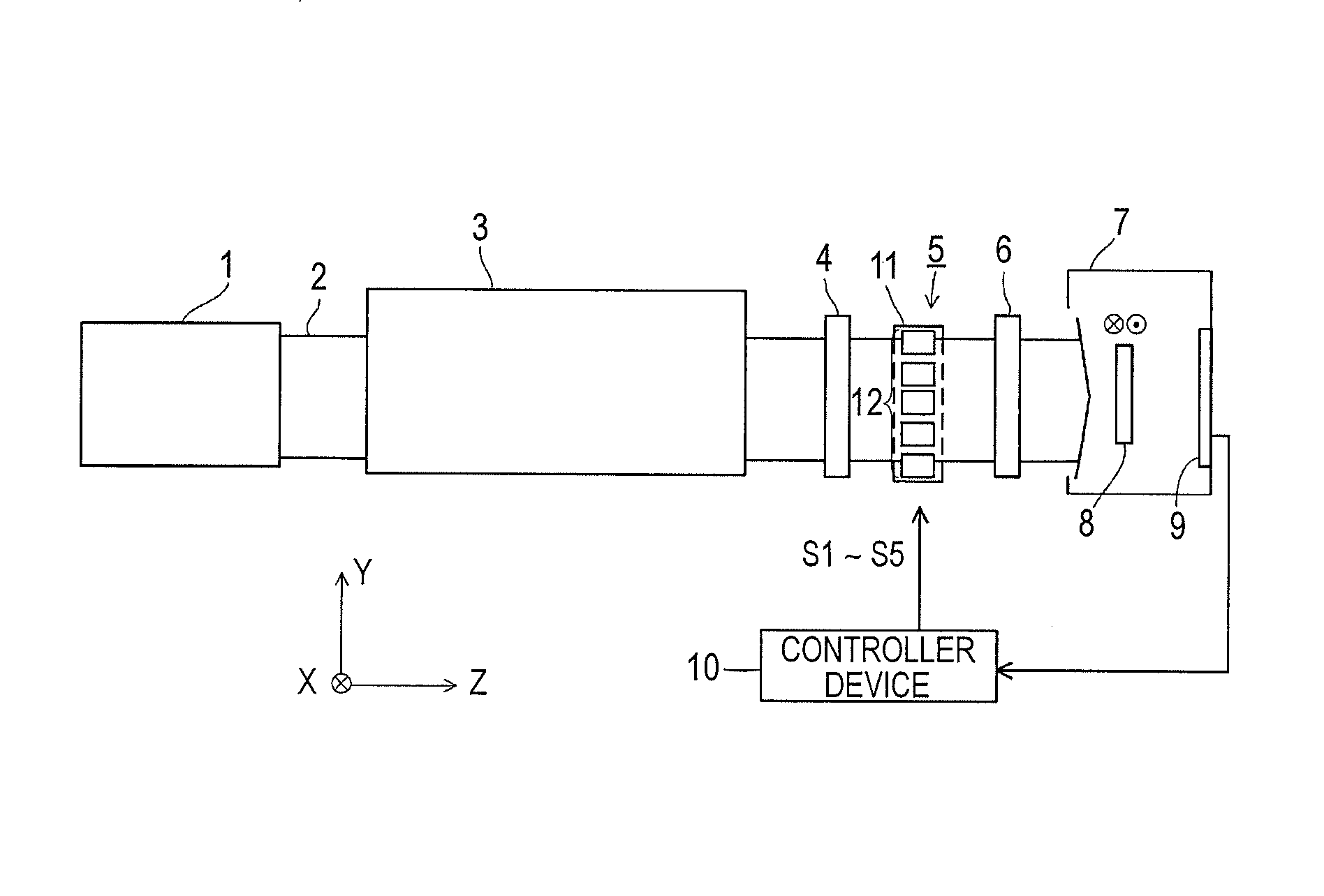
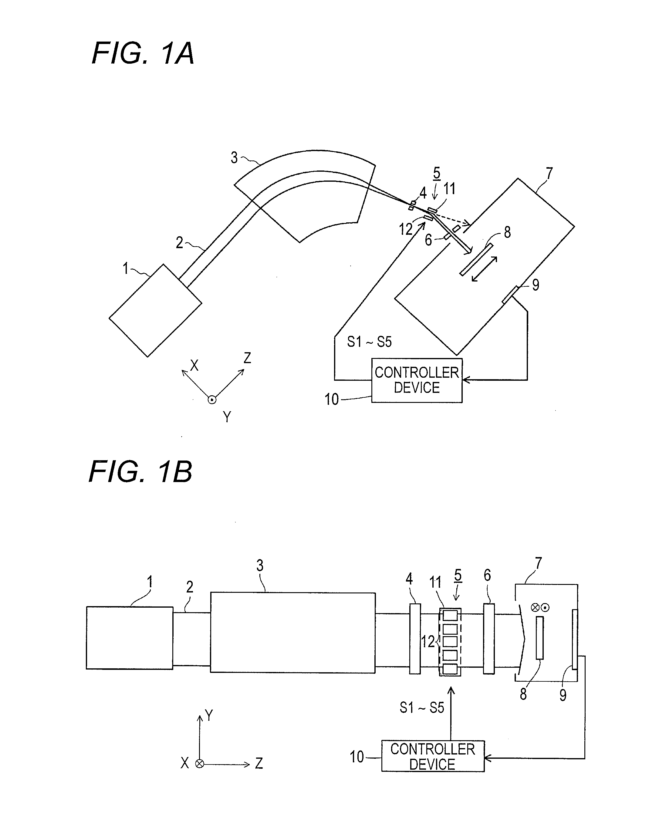
[0034]One example of an ion implanter according to the present invention is illustrated in FIG. 1. A ribbon-like ion beam of the present invention has a substantially rectangular cross section or a substantially ellipsoidal cross section when being cut in a plane perpendicular to a traveling direction of the ion beam. The ion beam may have a circular shape as well as the rectangular shape and the long ellipse shape in cross-section. In this embodiment, a Z-direction is referred to as a traveling direction of a ribbon-like ion beam, a Y-direction is referred to as a long side direction of the ribbon-like ion beam, and an X-direction is referred to as a short side direction of the ribbon-like ion beam. And, when the ion beam has the long ellipsoidal cross section, the Y-direction may be referred to as a long axis direction of the ion beam and the X-direction may be referred to as a short axis direction of the ion beam. Further, the ion beam dealt in the present invention is an ion bea...


PUM


Abstract

The ion implanter includes a deflecting electrode and a shield member. The ion beam has a ribbon shape. The deflecting electrode deflects at least a part of the ion beam in a long side direction toward a short side direction of the ion beam, based on a result measured of a beam current density distribution in the long side direction. The shield member partially shields the ion beam deflected by the deflecting electrode. The deflecting electrode includes a plate electrode and an electrode group including plural electrodes. The electrode group is disposed to face the plate electrode to interpose the ion beam between the plate electrode and the electrode group. The plate electrode is electrically grounded, and the plurality of electrodes are electrically independent from each other. Each of the plurality of electrodes is connected to an independent power source from other power sources to perform a potential setting.

Description

CROSS-REFERENCE TO RELATED APPLICATION(S)[0001]This application claims the benefit of Japanese Patent Application No.2011-178472, filed on Aug. 17, 2011, the entire contents of which are hereby incorporated by reference, the same as if set forth at length; the entire of which are incorporated herein by reference.TECHNICAL FIELD[0002]The present invention relates to an ion implanter including an electric field lens that adjusts a current density distribution in a longitudinal direction of a ribbon-like ion beam elongated in one direction.Related Art[0003]To deal with the increase in size of a substrate, an ion implanter utilizes a ribbon-like ion beam elongated in one direction. This ion beam has a substantially rectangular cross section when being cut in a plane perpendicular to a traveling direction of the ion beam. For example, the ion implanter transfers the substrate in a short side direction of the ribbon-like ion beam which is substantially perpendicular to a longitudinal dire...

Claims


Application Information

Patent Timeline
Patent Type & Authority Patents(United States)
IPC IPC(8): G21K5/04
CPCH01J37/3171H01J2237/30455H01J37/304H01J2237/30472H01J2237/0835H01J2237/31703H01J37/12H01J37/147H01J37/317
Inventor NAITO, MASAO
Owner NISSIN ION EQUIP CO LTD
Why Eureka
Try Eureka