
Automated patient-specific bone-implant biomechanical analysis

a biomechanical analysis and patient technology, applied in the field of orthopaedic surgical planning, can solve the problems of inability to analyze sometimes failing or loosening of implants, and inability to apply techniques to more than a few bones, etc., to achieve smooth deformation and facilitate use.

Active Publication Date: 2014-02-04
O N DIAGNOSTICS
View PDF16 Cites 34 Cited by
  • Summary
  • Abstract
  • Description
  • Claims
  • Application Information

AI Technical Summary

Benefits of technology

This patent describes a method for creating personalized bone implants by using a library of pre-constructed models. The method involves receiving a digital image of a bone, choosing a specific implant, and converting the image into a patient-specific model using advanced techniques. This allows for an automated process, eliminating the need for manual adjustment. The method also overcomes limitations of previous techniques and provides a more reliable basis for surgical planning. Additionally, the patent describes a technique for adapting the pre-constructed model for use with multiple implants that are in contact with each other and attached to the same bone but which have variable positions due to patient characteristics. This allows for improved analysis and planning during surgery. The resulting customized models can also be added to the library for future use. The overall approach provides greater automation, versatility, and accuracy for personalized bone implants.

Problems solved by technology

Orthopaedic implants and the bone they are implanted into often must endure large stresses from habitual and sporadic loading and consequently the implants sometimes fail or loosen.
While a number of references in the field have applied such finite element modeling techniques in research studies, for clinical implementation, a challenge is to automate this analysis to such a degree so that the analysis is available to a surgeon, radiologist, radiological imaging technician, or such other medical professional who has no technical expertise in finite element modeling.
There are no such techniques in the field for patient-specific modeling of bone-implant systems that meet all these criteria.
Indeed, regarding clinical implementation of such patient-specific bone-implant finite element analyses, Helwig et al. recently reported that such analyses “are not yet possible in daily routine as an automatic algorithm for biomechanical assessment does not exist” (Helwig P, Faust G, Hindenlang U, Kroplin B, and Eingartnew C, Technology and Health Care 14: 411-419, 2006).
Since this is a tedious process, this technique has never been applied to more than a few bones in a research setting.
One problem with this approach is that it is difficult to automate in a clinical setting due to the great degree of population variability in the geometry of the bones of patients.
Thus, while various methods for creation of such bone-implant meshes may work for regularly-sized and shaped bones, these algorithms typically require expert user input to deal with distorted elements in cases where the bone geometry is unusual or the implant geometry is complex.
These techniques can therefore not be applied to large numbers of patients in an automated manner in near real-time by persons unskilled in finite element analysis.
While automatic tetrahedral mesh generators can model the curvature of whole bones (see for example: GH Kwon, SW Chae, K J Lee, Computer and Structures 81:765-775, 2003; Viceconti M, Davinelli M, Taddei F, and Cappello A, Journal of Biomechanics 37: 1597-1605, 2004), the number of elements to do so in the presence of an implant would typically result in prohibitively large models that would be computationally very expensive to solve in a clinical context, particularly when one is to capture such implant detail as screw threads in the finite element mesh and small gaps between the implant and bone.
When using such autopaving, mesh distortion can also occur around the edges of some bones, particularly in regions of degenerative changes where the bone geometry becomes very irregular.
Mesh distortion is also an issue for use with deformable registration techniques, in which a “master” mesh of bone-implant system is “deformed” mathematically to fit the geometry of a digital image of a bone.
In a clinical situation, for certain patients with unusual bone geometries due to various types of pathology, highly distorted elements will inevitably result from such an automated meshing technique—especially when applied to a bone-implant situation.
As a result of these limitations, none of these prior art techniques have found any clinical use for bone-implant surgical planning purposes and there are no commercial applications of any such techniques that are suitable for clinical use.
However, this voxel-based approach provides a poor description of the surface of the implant because the geometry of the implant surface is forced to conform with the cube shape of the voxels.
Thus, this approach does not work well for curved implants, flat implants that are placed oblique to the coordinate system of the cube-shaped voxels, or any implants that contain complex non-voxel geometric features such as screw threads, fenestrations, holes, filets and the like.
Since maximum stresses in the implant typically occur on its surface and around such complex features, and since bone-implant interface stresses are key to assessing implant loosening, the use of such voxel-based meshes at the bone-implant interface is not desirable.
One additional issue that challenges full automation for clinical usage is the initial positioning and sizing of the implant within the bone.
Given the complex 3D nature of most bones, and the heterogeneity in bone density both with any bone from a given patient and across different patients, it is oftentimes difficult to properly size and position a given implant design for a given patient, and in some cases it is even difficult to choose between different implant designs for a given patient since some implants might work better in certain patients but worse in others due to the complex bone-implant load-transfer characteristics associated with the 3D nature of the bone geometry and the spatially varying distribution of bone density.

Method used


Image

  • Automated patient-specific bone-implant biomechanical analysis
  • Automated patient-specific bone-implant biomechanical analysis
  • Automated patient-specific bone-implant biomechanical analysis

Examples


Embodiment Construction

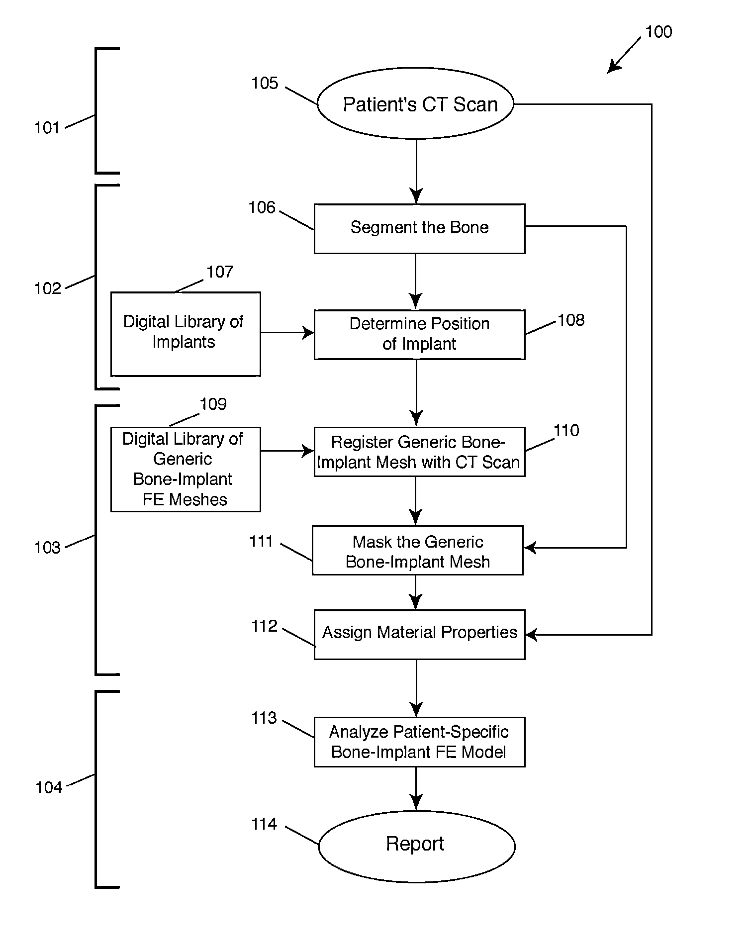
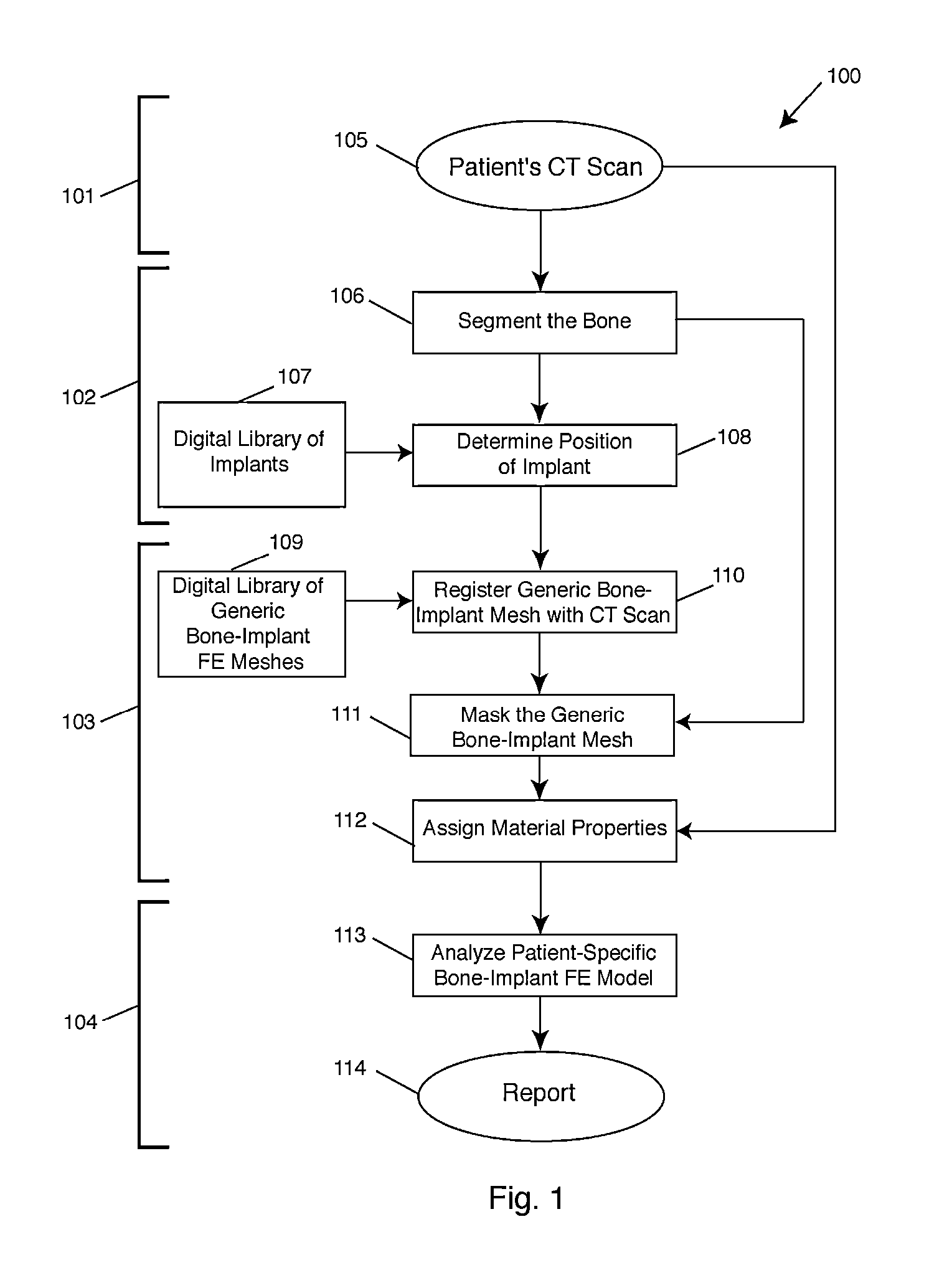
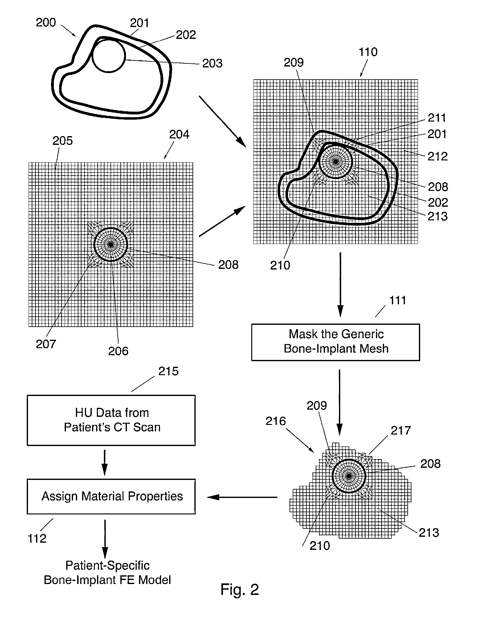
[0036]The present invention relates to surgical planning using a fully automated method of finite element modeling of bone-implant systems. The present invention may be used in a variety of clinical surgical planning applications, including but not limited to hip, spine, or knee surgery, total joint replacement, spinal fusion, pedicle screw fixation, and fracture fixation. While applicable to any clinical imaging modality—MRI, DXA, or X-rays—and to any bone-implant system, the technique is described in detail below for use with CT scans. In the following description, numerous specific details are set forth in order to provide a thorough understanding of the present invention. It will be apparent, however, to one skilled in the art, that the present invention may be practiced without some or all of these specified details and may be applied to any medical imaging modality and to any bone-implant system in which a goal is to perform a biomechanical analysis of such bone-implant system...


PUM


Abstract

An apparatus, method, and computer program product for providing information for surgical planning based on automated biomechanical analysis of a bone-implant system using finite element analysis of a patient's 3D medical image, including automated biomechanical analysis of bone-implant systems for use in surgical planning both pre-operatively and intra-operatively and for use in research and development studies.

Description

CROSS REFERENCE TO RELATED APPLICATIONS[0001]This application is a Continuation-In-Part of U.S. application Ser. No. 12 / 510,225, filed 27 Jul. 2009 which claims the benefit of U.S. Provisional Application No. 61 / 083,875, filed Jul. 25, 2008, entitled AUTOMATED PATIENT-SPECIFIC BONE-IMPLANT BIOMECHANICAL ANALYSIS, the disclosures of which are herein incorporated by reference in their entireties for all purposes.BACKGROUND OF THE INVENTION[0002]The present invention relates generally to a method and system for orthopaedic surgical planning and more specifically to surgical planning based on an automated finite element analysis of a bone-implant system using a 3D medical image of a patient.[0003]Orthopaedic implants and the bone they are implanted into often must endure large stresses from habitual and sporadic loading and consequently the implants sometimes fail or loosen. Biomechanical analysis of a bone-implant system is often performed as part of the design process for such implant...

Claims


Application Information

Patent Timeline
Patent Type & Authority Patents(United States)
IPC IPC(8): G06K9/00
CPCG06T2210/41A61B5/4851A61B6/032G06T19/20G06K2209/057G06T7/0012G16H20/40G16H30/40G16H50/50G06V2201/034
Inventor HOFFMANN, PAUL F.KEAVENY, TONY M.KOPPERDAHL, DAVID L.
Owner O N DIAGNOSTICS
Learn More