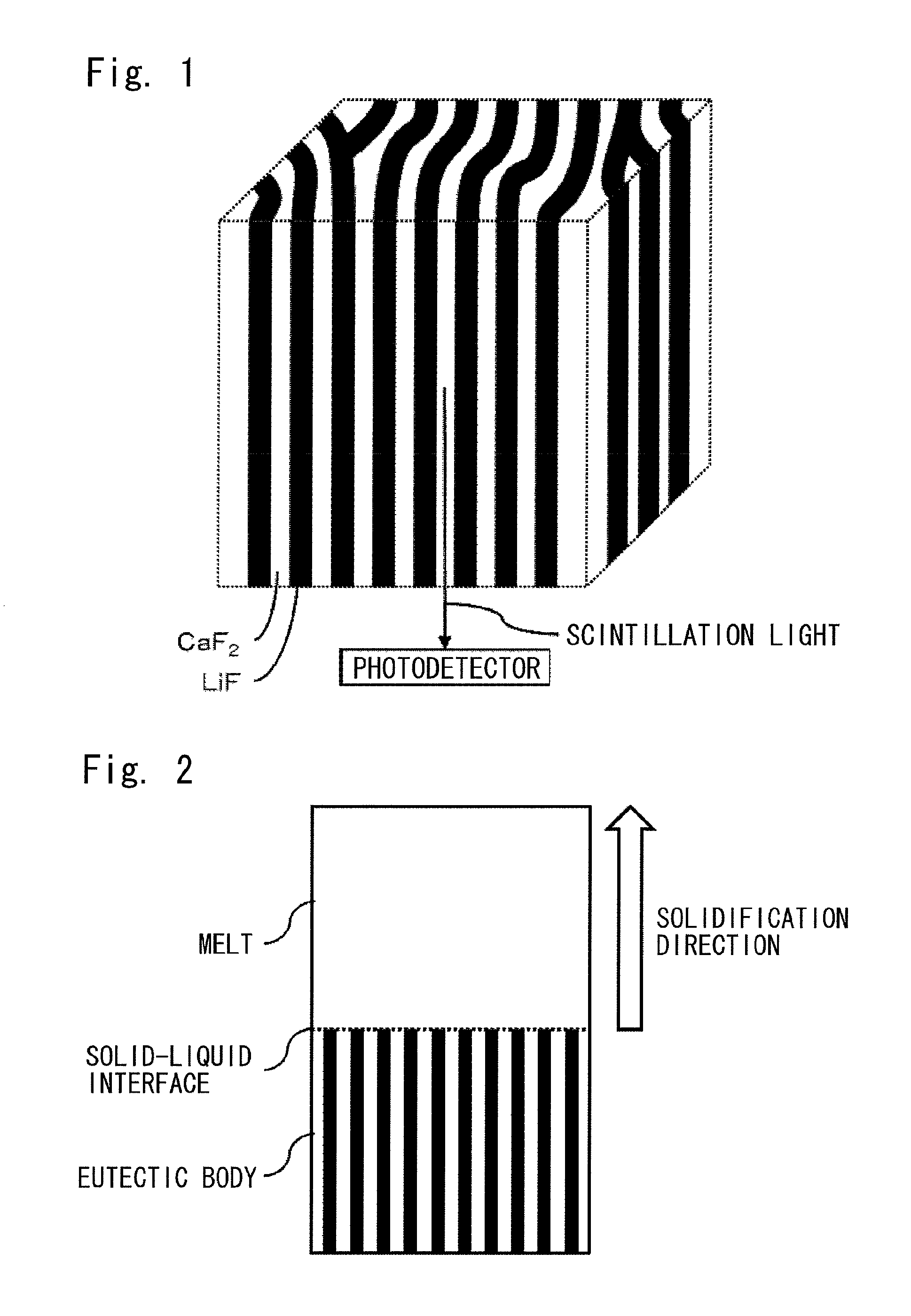
Neutron scintillator and neutron detector

a neutron detector and scintillator technology, applied in the field of neutron scintillators, can solve the problems of limited count rate, so-called background noise increase, and high cost of helium-3, and achieve excellent n/ discrimination ability and high neutron detection efficiency

Inactive Publication Date: 2014-02-04
TOKUYAMA CORP +1
View PDF3 Cites 5 Cited by
  • Summary
  • Abstract
  • Description
  • Claims
  • Application Information

AI Technical Summary

Benefits of technology

[0027]According to the present invention, a neutron scintillator having high neutron detection efficiency and excellent n / γ discrimination ability can be provided. A neutron detector using such a neutron scintillator can be preferably used in scientific research fields such as structural analyses by neutron diffraction, nondestructive inspection fields, or security fields such as cargo inspection.

Problems solved by technology

If the n / γ discrimination ability is low, therefore, a signal which does not reflect the interaction between neutrons and the object to be tested enters, and a so-called background noise increases.
This detector has high detection efficiency and excellent n / γ discrimination ability, but has posed the problem of a limited count rate.
Moreover, helium-3 is an expensive substance and its resources are limited.
Since the LiF / ZnS is opaque, however, an increase in its thickness has made it impossible to take out scintillation light (scintillation) efficiently.
Thus, the LiF / ZnS has been limited in the improvement of neutron detection efficiency.
According to studies by the inventors of the present invention, however, the neutron scintillator at issue involves great variations in the brightness of scintillation light when detecting neutrons, and thus has posed difficulty in discriminating between neutrons and gamma rays.
Nor has any study been conducted on the application of the eutectic body as a neutron scintillator, and no findings have been presented in connection with the thickness of the crystal layers and the layered structure preferred for a neutron scintillator.

Method used


Image

  • Neutron scintillator and neutron detector
  • Neutron scintillator and neutron detector
  • Neutron scintillator and neutron detector

Examples


example 1

Production of Eutectic Body

[0069]Lithium fluoride (331 g), calcium fluoride (258 g), and europium fluoride (3.45 g), as starting materials, were mixed to prepare a material mixture. Each starting material used was a powder with purity of 99.99% or more. As lithium fluoride, a material having a 6Li-isotope ratio of 95% was used. The component ratio between lithium fluoride and calcium fluoride in the material mixture was 0.8 mol lithium fluoride: 0.2 mol calcium fluoride, and the amount of europium, as a luminescence center element, contained in CaF2 crystals was 0.5 mol % with respect to CaF2.

[0070]Then, the material mixture was charged into a crucible formed of carbon and having an internal diameter of 60 mm, and the crucible was installed in a chamber equipped with a resistance heating type heater, a heat insulator, and a vacuum evacuator. Using the vacuum evacuator, the interior of the chamber was evacuated to 2.0×10⁻⁴ Pa or lower. Then, a high purity argon gas mixed with 5 vol %...

example 2

Production of Eutectic Body

[0083]A eutectic body was obtained in the same manner as in Example 1, except that the solidification rate was set at 3 mm / hr. The resulting eutectic body was observed for a compositional backscattered electron image in the same manner as in Example 1. A compositional backscattered electron image of a surface of the eutectic body when cut in a direction parallel to the solidification direction is shown in FIG. 7. A compositional backscattered electron image of a surface of the eutectic body when cut in a direction perpendicular to the solidification direction is shown in FIG. 8.

[0084]FIG. 7 shows that CaF2 crystal layers were linearly continuous in one direction. In connection with the compositional backscattered electron image of FIG. 8, the thickness of the LiF crystal layer was measured using the length measuring function of the SEM. The thickness of the layer of LiF in the eutectic body was found to be 4 μm. Powder X-ray diffraction measurement was per...

preparation example 2

Preparation and Characteristics Evaluation of Neutron Detector

[0086]The response characteristics of the neutron scintillator (i.e., response to neutrons) were evaluated in the same manner as in Example 1. FIG. 6 shows a pulse height spectrum obtained when the neutron scintillator of Preparation Example 1 was used. FIG. 9 shows, and compares, pulse height spectra obtained when the neutron scintillators of Preparation Example 1 and Preparation Example 2 were used.

[0087]Clear peaks indicating the detection of neutrons were confirmed from FIG. 6. Thus, it has been found that the eutectic body of the present invention acts effectively as a neutron scintillator, and that a neutron detector using the neutron scintillator is effective. As in Example 1, the peaks showing the detection of neutrons can be clearly distinguished from gamma-ray noises. Hence, the neutron scintillator of the present invention has been found to have excellent n / γ discrimination ability.

[0088]The pulse height spectr...


PUM


Abstract

[Problems to be Solved] A neutron scintillator excellent in neutron detection efficiency and n / γ discrimination ability, and a neutron detector using the neutron scintillator are provided.[Means to Solve the Problems] A neutron scintillator comprising a eutectic body composed of laminar lithium fluoride crystals and laminar calcium fluoride crystals alternately arranged in layers, the thickness of the lithium fluoride crystal layers in the eutectic body being 0.1 to 5 μm; or a neutron scintillator comprising a eutectic body composed of laminar lithium fluoride crystals and laminar calcium fluoride crystals alternately arranged in layers, the calcium fluoride crystal layers in the eutectic body being linearly continuous in at least one direction; and a neutron detector basically constructed from any of the neutron scintillators and a photodetector.

Description

TECHNICAL FIELD[0001]This invention relates to a neutron scintillator comprising a eutectic body, and a neutron detector composed of the neutron scintillator and a photodetector. More specifically, the invention relates to a neutron scintillator comprising a eutectic body in which laminar lithium fluoride crystals and laminar calcium fluoride crystals are arranged in layers with a specific structure.BACKGROUND ART[0002]Neutron detectors are an elemental technology supporting neutron application technologies. With the progress of the neutron application technologies in scientific research fields such as structural analyses by neutron diffraction, nondestructive inspection fields, or security fields such as cargo inspection, there is a demand for a neutron detector which achieves higher performance.[0003]Main performances demanded of the neutron detector are the detection efficiency and the count rate of neutrons, and the ability to discriminate between neutrons and gamma rays (may he...

Claims


Application Information

Patent Timeline
Patent Type & Authority Patents(United States)
IPC IPC(8): G01T3/06
CPCG01T3/06G21K4/00C09K11/7733
Inventor FUKUDA, KENTAROISHIZU, SUMITOKAWAGUCHI, NORIAKISUYAMA, TOSHIHISAYOSHIKAWA, AKIRAYANAGIDA, TAKAYUKIYOKOTA, YUI
Owner TOKUYAMA CORP
Why Eureka
Try Eureka