
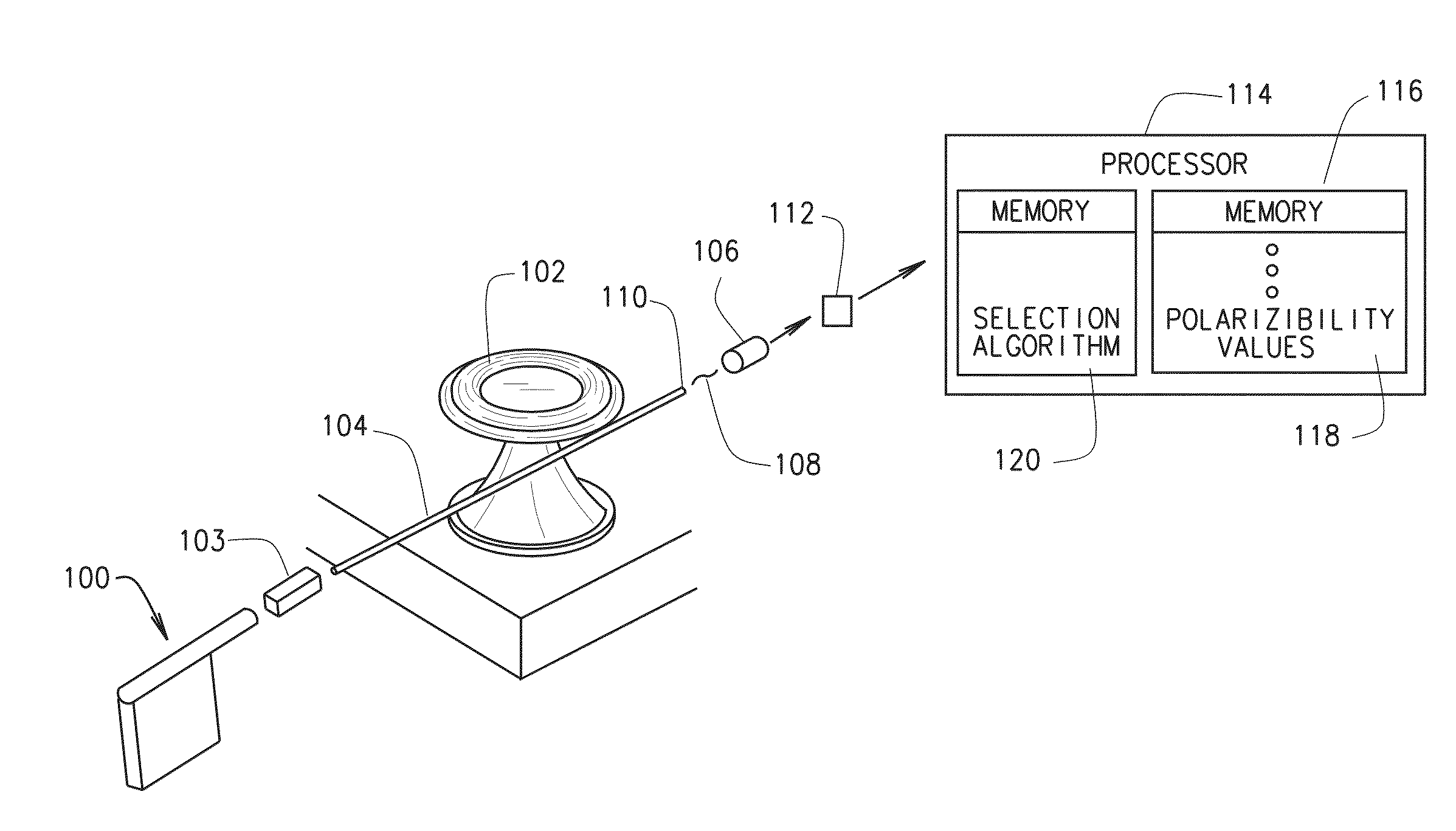
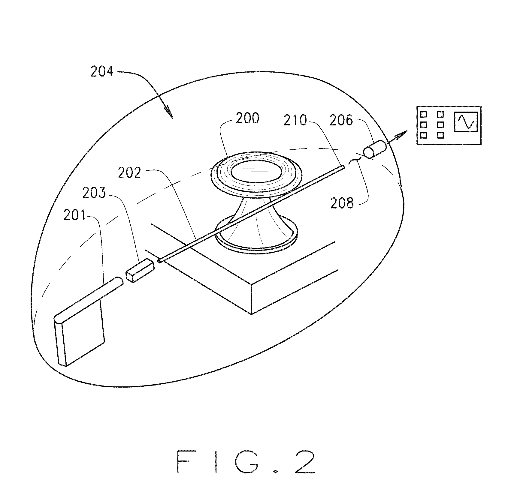
Micro-resonator and fiber taper sensor system

a micro-resonator and sensor system technology, applied in the direction of nanoparticle analysis, instruments, material analysis, etc., can solve the problems of high cost, high sensitivity and resolution, and the known particle detection system uses conventional microscopic techniques, etc., to achieve the effect of optimizing performance and ensuring accuracy

Inactive Publication Date: 2016-09-15
WASHINGTON UNIV IN SAINT LOUIS
View PDF2 Cites 20 Cited by
  • Summary
  • Abstract
  • Description
  • Claims
  • Application Information

AI Technical Summary

Benefits of technology

The technology described in this patent uses methods for sensing particles using mode splitting or frequency shift. It can select particles based on their polarization measurement, and can also make portable and on-chip sensors using micro-resonator technology. The use of a polarizer can optimize the performance of the resonator. The mode splitting occurs due to the coupling of counter-propagating double-degenerate resonators, which results in two standing wave modes with different resonance frequencies and linewidths. This allows for highly sensitive and label-free detection of particles. The technology also avoids the issue of bulky size and alignment issues by using nano-couplers based on cavity enhanced Rayleigh scattering from nano-scatterers on the resonator surface. Overall, this technology expands the range of applications enabled by WGMRs and can be integrated into solar powered green photonics.

Problems solved by technology

At least some known particle detection systems use conventional microscopic techniques which, despite their high sensitivity and resolution, may not be suitable for field measurements due to their expensive and bulky constructions, long processing times, and the necessity of pretreatment (labeling with fluorescent dyes, etc.) of the particles.
These sensors generally require a fiber taper to couple the light into and out of the resonator from a tunable laser, whose wavelength is continuously scanned to monitor the changes in the resonance modes, thus making these highly compact and sensitive sensors relatively expensive.
Constructive or destructive interference between multiple reflections between two or more reflecting surfaces can occur.
However, decreasing the resonator size below a critical value inevitably increases bending losses and eventually decreases Q. Instead, hybrid systems combining high-Q WGMs with highly confined (small-V) localized plasmons have been demonstrated, achieving detection of single proteins and very small viruses.
Use of dopants make the fabrication process complicated (i.e., one has to find ways of doping the resonators), costly (rare-earth ions, quantum dots and dyes are expensive, and new fabrication processes add to the cost) and introduce biocompatibility issues.
For example, silica is a biocompatible material; however, rare-earth-ions are not biocompatible.
Therefore, doping silica WGM resonator with a rare-earth-ion destroys biocompatibility.
However, fabricating WGM-plasmon hybrids and active WGMRs with dopants introduces additional processing steps and costs.
For example, WGM-plasmon hybrids require preparation and adsorption of plasmonic nano-structures onto the resonator surface, and active resonators suffer from the fact that most rare-earth ions are not biocompatible and that for each different wavelength band of operation a different rare-earth ion and a different pump laser should be used.

Method used


Image

  • Micro-resonator and fiber taper sensor system
  • Micro-resonator and fiber taper sensor system
  • Micro-resonator and fiber taper sensor system

Examples


Embodiment Construction

[0057]According to the embodiment(s) of the present invention, various views are illustrated in FIG. 1-9 and like reference numerals are being used consistently throughout to refer to like and corresponding parts of the invention for all of the various views and figures of the drawing. Also, please note that the first digit(s) of the reference number for a given item or part of the invention should correspond to the FIG. number in which the item or part is first identified.

[0058]This application claims the benefit of and priority to U.S. Provisional Application Ser. No. 62 / 113,610, Filed Feb. 9, 2015, entitled MICRORESONATOR AND FIBER TAPER BASED SENSOR SYSTEMS, which is hereby incorporated in its entirety herein.

[0059]One implementation of the present technology comprising a micro-resonator and fiber taper based system teaches an apparatus and method for sensing particles. By way of background, particle binding splits a WGM into two spectrally shifted resonance modes, forming a sel...


PUM

PropertyMeasurementUnit
radiusaaaaaaaaaa
polarizabilityaaaaaaaaaa
transmissionaaaaaaaaaa

Abstract

A micro-resonator and fiber taper based sensing system, which uses mode splitting or frequency shift methods and polarization measurements for particle sensing.

Description

CROSS REFERENCE[0001]This application claims the benefit of and priority to U.S. Provisional Application Ser. No. 62 / 113,610, Filed Feb. 9, 2015, entitled MICRORESONATOR AND FIBER TAPER BASED SENSOR SYSTEMS, which is hereby incorporated in its entirety herein.[0002]This invention was made with government support under NSF 0954941 awarded by the National Science Foundation and W911NF-12-1-0026 awarded by the U.S. Army Research Office. The government has certain rights in the invention.BACKGROUND[0003]1. Field[0004]This technology relates generally to sensing micro and nanoscale particles, and more particularly, to nanoscale sensing and wave sensing / detection using micro-resonators[0005]2. Background Art[0006]Interest in nanoparticle detection and characterization techniques has increased with the increasing awareness of the potential benefits and risks of the continuously generated byproduct or massively synthesized nano-particles. Nano-particles of special interests range from biolo...

Claims


Application Information

Patent Timeline
Patent Type & Authority Applications(United States)
IPC IPC(8): G01N33/543G01N15/14G01N21/45
CPCG01N33/54373G01N21/45G01N15/1429G01N15/1434G01N2201/08G01N2021/458G01N21/21G01N2201/0683G01N2201/06113G01N2015/1454G01N2015/0038G01N21/7746G01N15/1433
Inventor OZDEMIR, SAHIN KAYAYANG, LAN
Owner WASHINGTON UNIV IN SAINT LOUIS
Learn More