Semiconductor device and fabrication method thereof
a semiconductor device and semiconductor technology, applied in the direction of semiconductor devices, basic electric elements, electrical equipment, etc., can solve the problems of strong electric field, and achieve the effect of reducing production costs and saving space on wafers
- Summary
- Abstract
- Description
- Claims
- Application Information
AI Technical Summary
Benefits of technology
Problems solved by technology
Method used
Image
Examples
embodiment 1
[0030]FIG. 3A depicts layout structure of a semiconductor device according to the embodiment of the invention, FIG. 3B is an enlarged view of one finger of the drain and the gate at corresponding position in FIG. 3A, and FIG. 4 depicts a cross-section view along line A-A in layout structure of the semiconductor device of FIG. 3A.
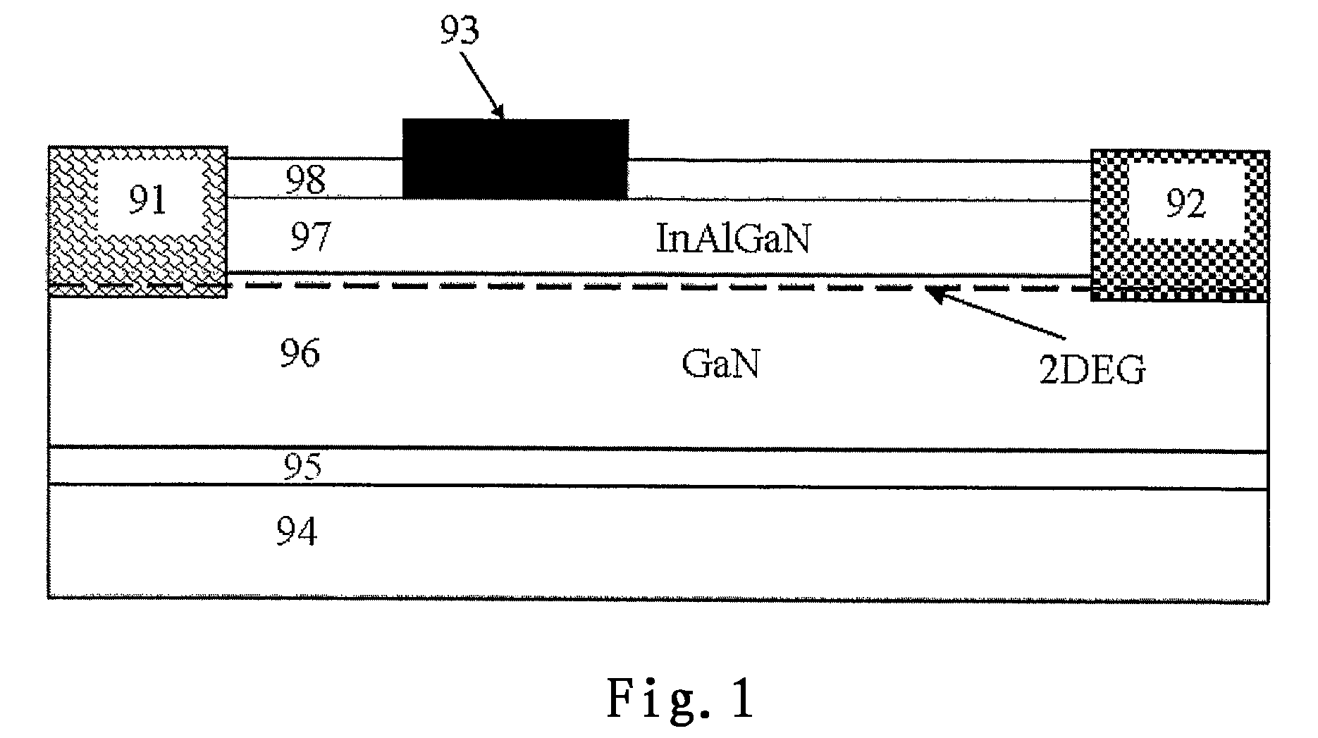
[0031]Next, basic structure of an enhancement mode GaN HEMT of the embodiment as an example of semiconductor device will first be described with reference to FIG. 4
[0032]As shown in FIG. 4, under layer is a substrate 54 for growing GaN material, which generally is Sapphire, SiC, GaN, Si or any other substrates known in the art suitable for growing GaN material, and the invention has no limitation on this.
[0033]On the substrate 54 is an optional nucleation layer 55 for growing a semiconductor layer thereon. It should be appreciated that, instead of forming the nucleation layer 55, a semiconductor layer may also be directly formed on the substrate 54.
[0034]On ...
embodiment 2
[0047]FIG. 5 depicts a layout structure of a semiconductor device according to another embodiment of the invention.
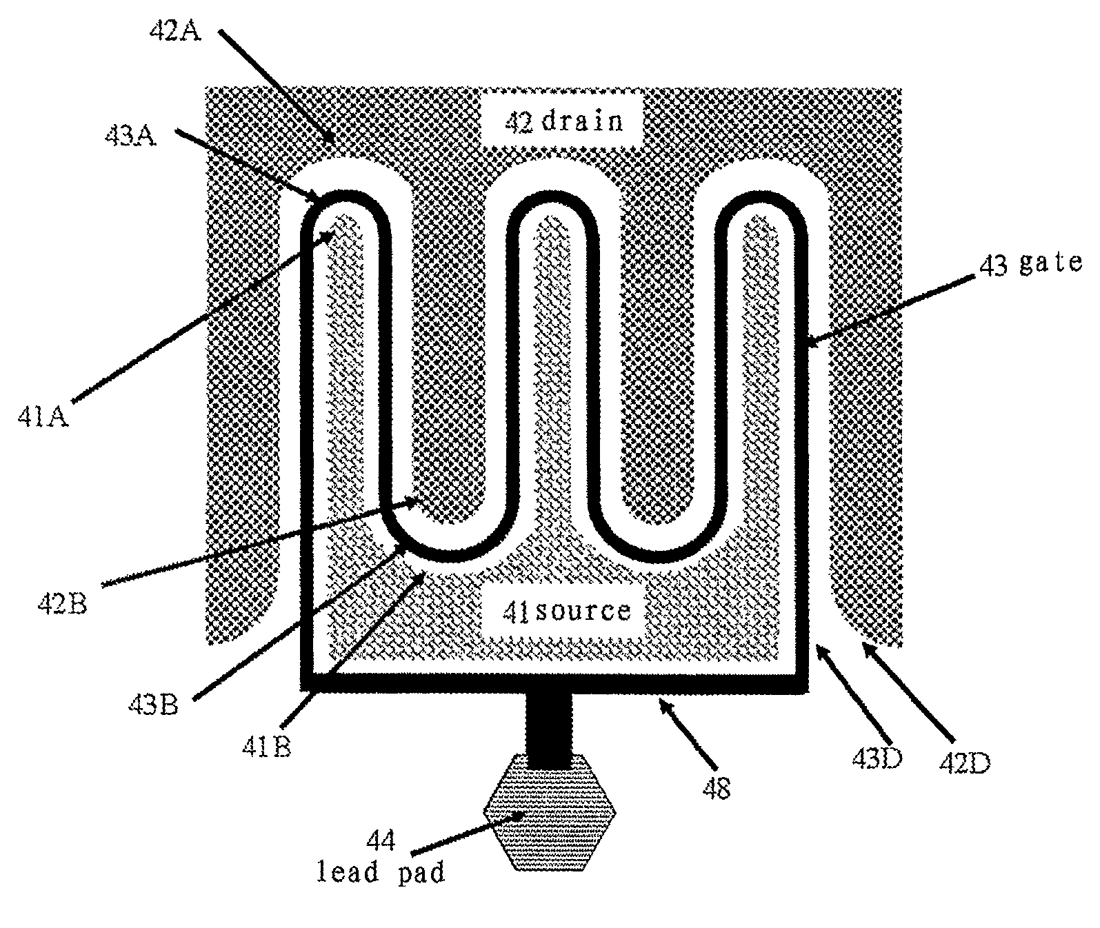
[0048]As shown in FIG. 5, this embodiment is the same as the embodiment 1 shown in the above FIG. 3A in that, the source 41 and the drain 42 comprise intersected multiple fingers 41A, 42B, and the gate 43 is located between the source 41 and the drain 42, and forms a closed ring structure encircling the multiple fingers 41A of the source 41 and the multiple fingers 42B of the drain 42. Description of portions of embodiment 2 that are same as that of embodiment 1 will be omitted herein, and emphasis will be put on difference of the two.
[0049]Embodiment 2 differs from embodiment 1 in two points. First, the gate 43 with closed ring structure entirely encircles the source 41, and the drain 42 is located at peripheral of the gate 43. Second, starting and ending point of the gate 43 are not directly connected, instead, they are connected through an interconnection line 48, wh...
embodiment 3
[0052]FIG. 6 depicts a layout structure of a semiconductor device according to another embodiment of the invention.
[0053]As shown in FIG. 6, this embodiment is the same as the embodiment 2 shown in the above FIG. 5 in that, the source 41 and the drain 42 comprise intersected multiple fingers 41A, 42B, and the gate 43 is located between the source 41 and the drain 42, and forms a closed ring structure encircling the multiple fingers 41A of the source 41 and the multiple fingers 42B of the drain 42, and starting point and ending point of the gate 43 are not directly connected, rather, they are connected through an interconnection line. Description of portions of embodiment 3 that are same as that of embodiment 2 will be omitted herein, and emphasis will be put on difference of the two.
[0054]Embodiment 3 differs from embodiment 2 in that the gate 43 entirely encircles the drain 42, and the source 41 is located at peripheral of the gate 43.
[0055]In this embodiment, a sharp right angle 4...
PUM
 Abstract
Description
Claims
Application Information
 - R&D
- Intellectual Property
- Life Sciences
- Materials
- Tech Scout
- Unparalleled Data Quality
- Higher Quality Content
- 60% Fewer Hallucinations
Browse by: Latest US Patents, China's latest patents, Technical Efficacy Thesaurus, Application Domain, Technology Topic, Popular Technical Reports.
© 2025 PatSnap. All rights reserved.Legal|Privacy policy|Modern Slavery Act Transparency Statement|Sitemap|About US| Contact US: help@patsnap.com


