
Gas turbine engine breather exhaust oil collector

a technology for gas turbine engines and exhaust oil collectors, which is applied to engines, mechanical equipment, machines/engines, etc., can solve the problems of oil loss, oil mist and vapour remaining in the vented air, oil loss, etc., and achieves the effect of preventing oil loss and preventing oil loss

Active Publication Date: 2014-01-07
PRATT & WHITNEY CANADA CORP
View PDF31 Cites 20 Cited by
  • Summary
  • Abstract
  • Description
  • Claims
  • Application Information

AI Technical Summary

Benefits of technology

This patent is about a gas turbine engine oil system that removes air from oil and directs hot air to a cooler chamber, where the oil vaporizes and is collected. The system also has a breather tube that allows air and oil to exchange with cooler air outside the tube. This results in a two-way fluid exchange that prevents fouling and ensures the oil is returned to the engine at shut down. The system also includes an oil collector that cool the hot air and returns the oil to the engine oil system. The technical effect of this system is to improve engine oil health and prevent damage from high temperatures.

Problems solved by technology

One problem is that oil mist and vapour remains in the vented air.
Venting thus results in some oil loss.
The oil loss can stain the engine or nacelle, pollute the environment and require larger oil reserve onboard engine.

Method used


Image

  • Gas turbine engine breather exhaust oil collector
  • Gas turbine engine breather exhaust oil collector
  • Gas turbine engine breather exhaust oil collector

Examples


Embodiment Construction

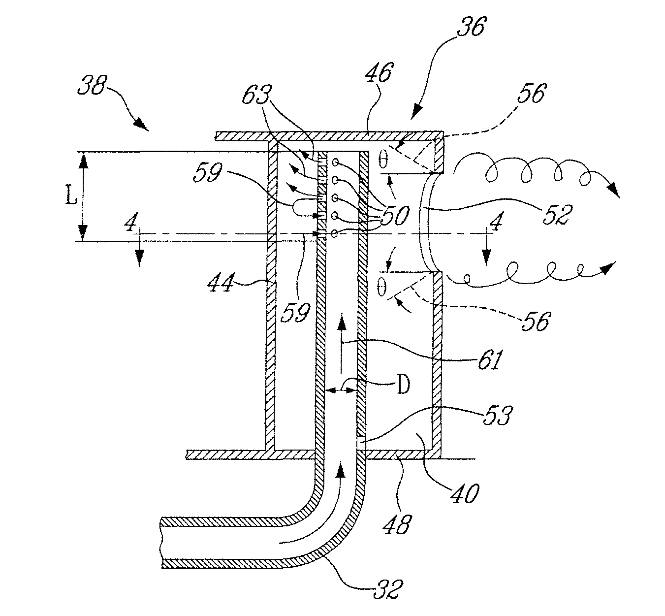
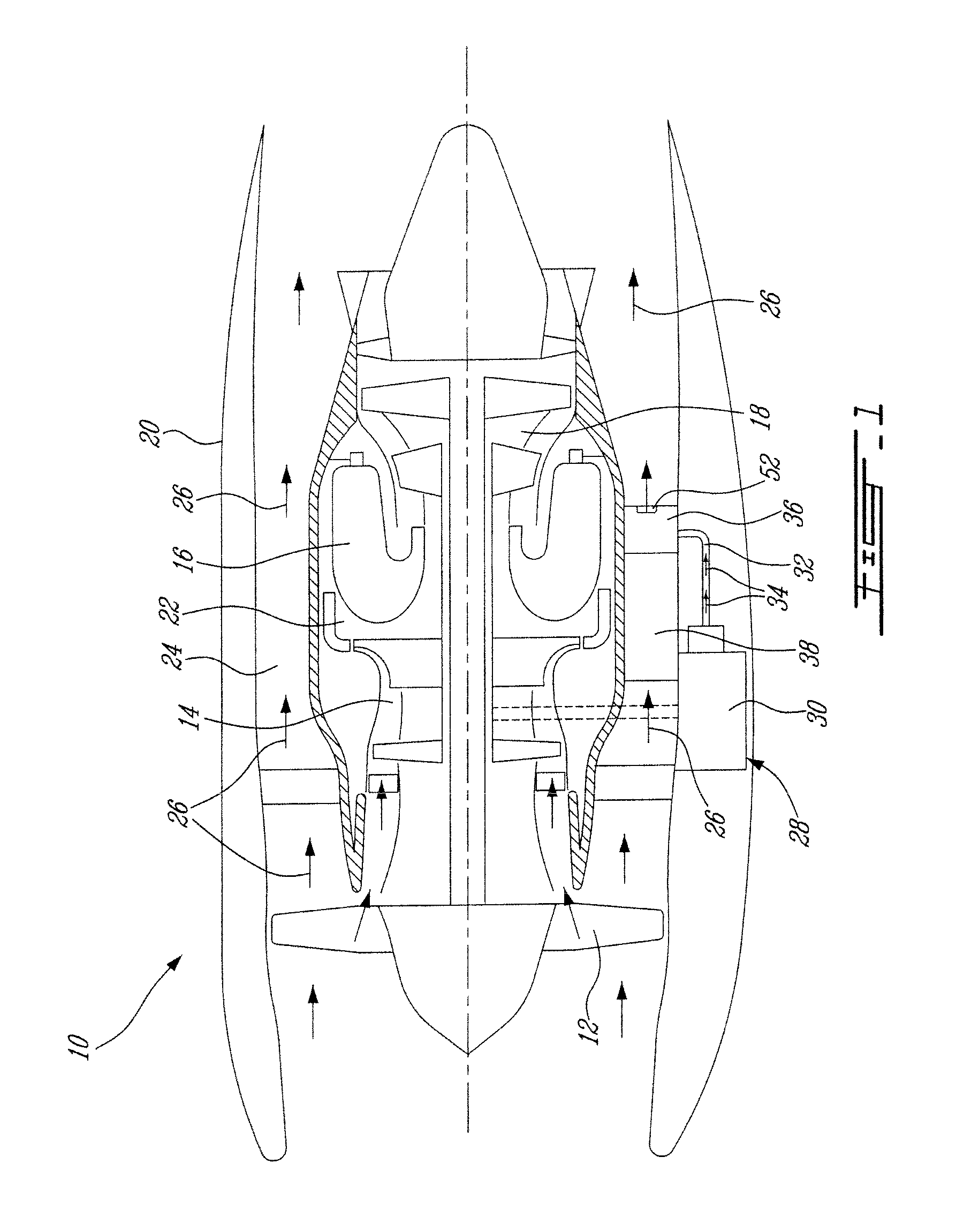
[0013]FIG. 1 illustrates a turbofan gas turbine engine 10 of a type preferably provided for use in subsonic flight, generally comprising in serial flow communication a fan 12 through which ambient air is propelled, a multistage compressor 14 for pressurizing the air, a combustor 16 in which the compressed air is mixed with fuel and ignited for generating an annular stream of hot combustion gases, and a turbine section 18 for extracting energy from the combustion gases. The gas turbine engine includes a nacelle or outer casing 20 surrounding an inner casing 22 enclosing the core engine. The nacelle 20 is spaced from the inner casing 22 providing an annular bypass passage 24 for flow of air from the fan 12 to the exhaust of the engine, as depicted by arrows 26.

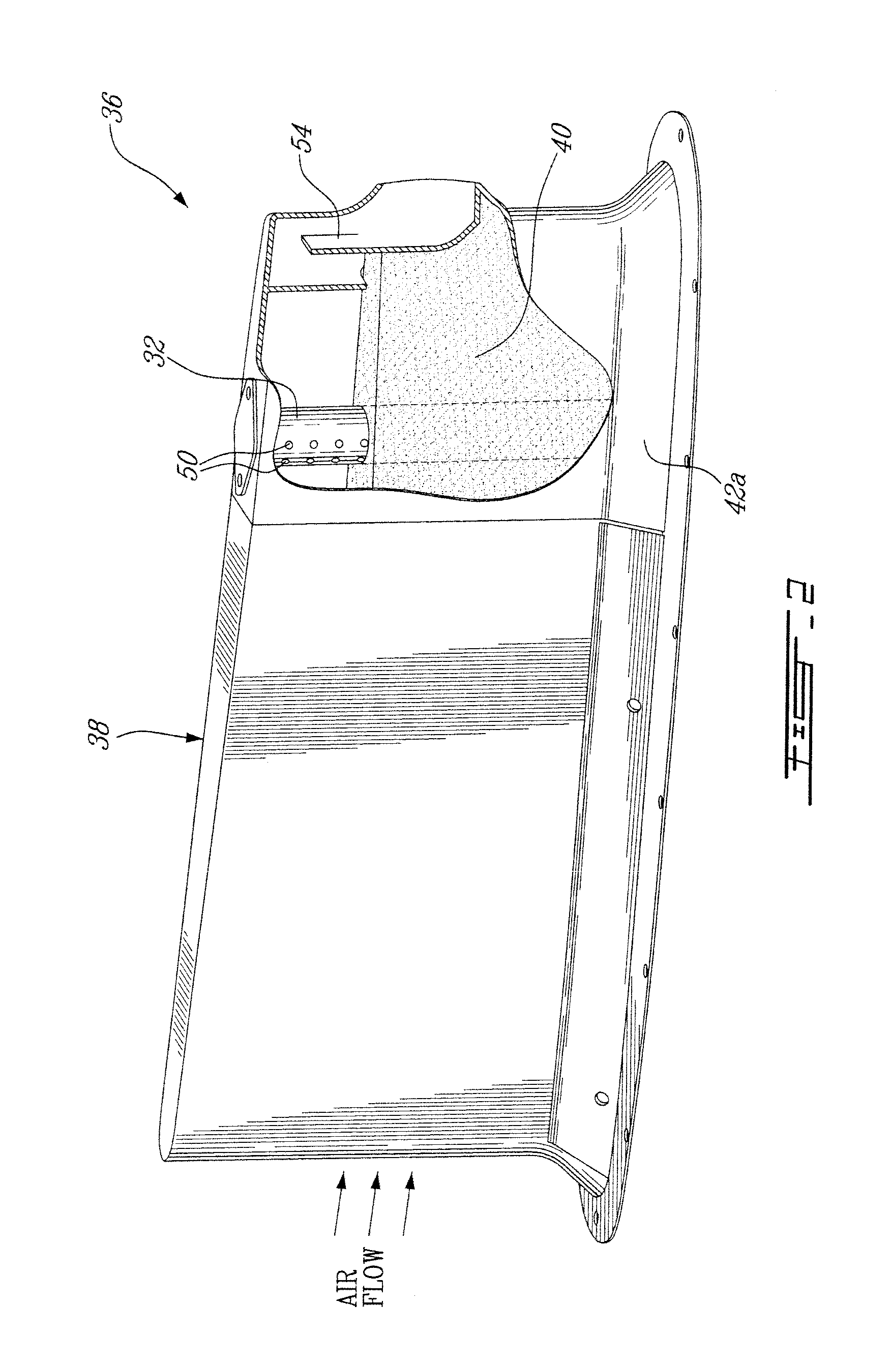
[0014]An accessory gear box (AGB) 28 driven by the high pressure rotor of the engine 10 provides drive for the engine accessories (not shown). The AGB 28 also provides a sump area for the engine bearing and gear scavenge oil to ...


PUM


Abstract

A gas turbine engine oil system has an air-oil separator for removing air from an air / oil mixture. A breather tube is connected to an exhaust of the air-oil separator for receiving hot air removed from the air / oil mixture in the air-oil separator. The gas turbine engine oil separator exhaust is directed in a cooled oil collector to cause the oil mist remaining in the air at the exit from the engine air-oil separator to condensate. The oil condensate is returned back into the engine oil system.

Description

TECHNICAL FIELD[0001]The application relates generally to gas turbine engines and, more particularly, to turbine oil systems.BACKGROUND OF THE ART[0002]Gas turbine engine oil systems ingest air in the bearing cavities, and thus a breather (also know as an air-oil separator) is provided to remove air from oil. The breather is vented to allow the air to escape. One problem is that oil mist and vapour remains in the vented air. Venting thus results in some oil loss. The oil loss can stain the engine or nacelle, pollute the environment and require larger oil reserve onboard engine.[0003]Accordingly, there is a need to provide an improved gas turbine engine oil system.SUMMARY[0004]In one aspect, there is provided a gas turbine engine oil system comprising an air-oil separator for removing air from an air / oil mixture, a breather tube connected to an exhaust of the air-oil separator for receiving hot air removed from the air / oil mixture in the air-oil separator, the hot air still carrying ...

Claims


Application Information

Patent Timeline
Patent Type & Authority Patents(United States)
IPC IPC(8): F02C7/06F01D25/18
CPCF05D2260/60F02C7/06F05D2260/20F01D25/20
Inventor ALECU, DANIEL T.OLVER, BRYAN WILLIAM
Owner PRATT & WHITNEY CANADA CORP
Learn More