Programmable logic device
a programmable logic and semiconductor technology, applied in the direction of power consumption reduction, pulse technique, instruments, etc., can solve the problems of long delay time, loss of configuration data stored in the memory portion, and difficulty in performing normal-off driving methods in which supply of power supply potential is temporarily stopped, so as to reduce the power consumption the start-up time of a programmable logic device can be short, and the off-state current is sufficiently reduced.
- Summary
- Abstract
- Description
- Claims
- Application Information
AI Technical Summary
Benefits of technology
Problems solved by technology
Method used
Image
Examples
embodiment 1
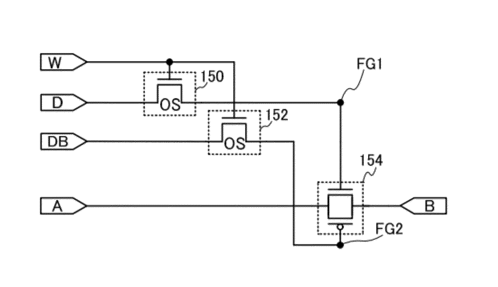
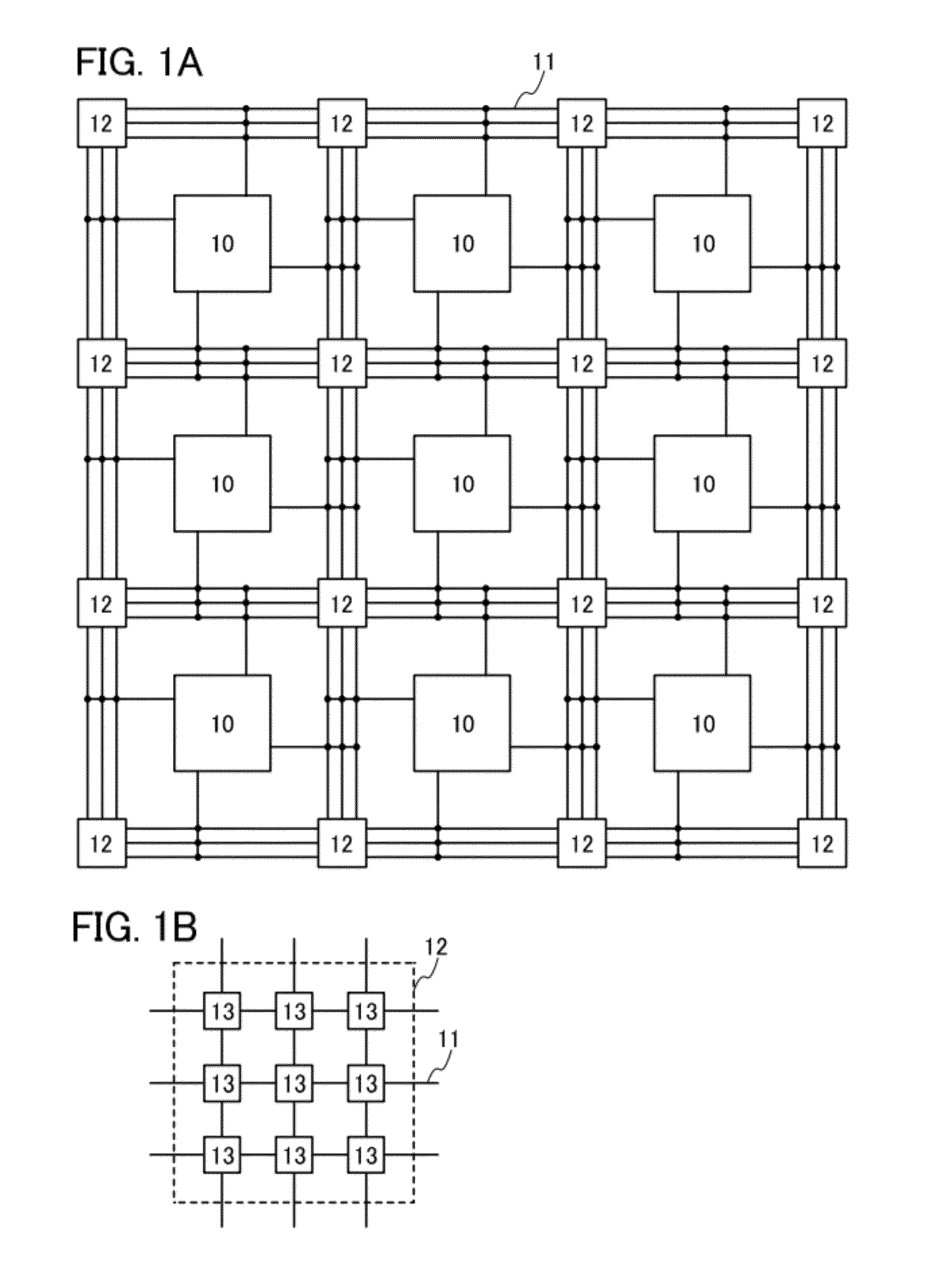
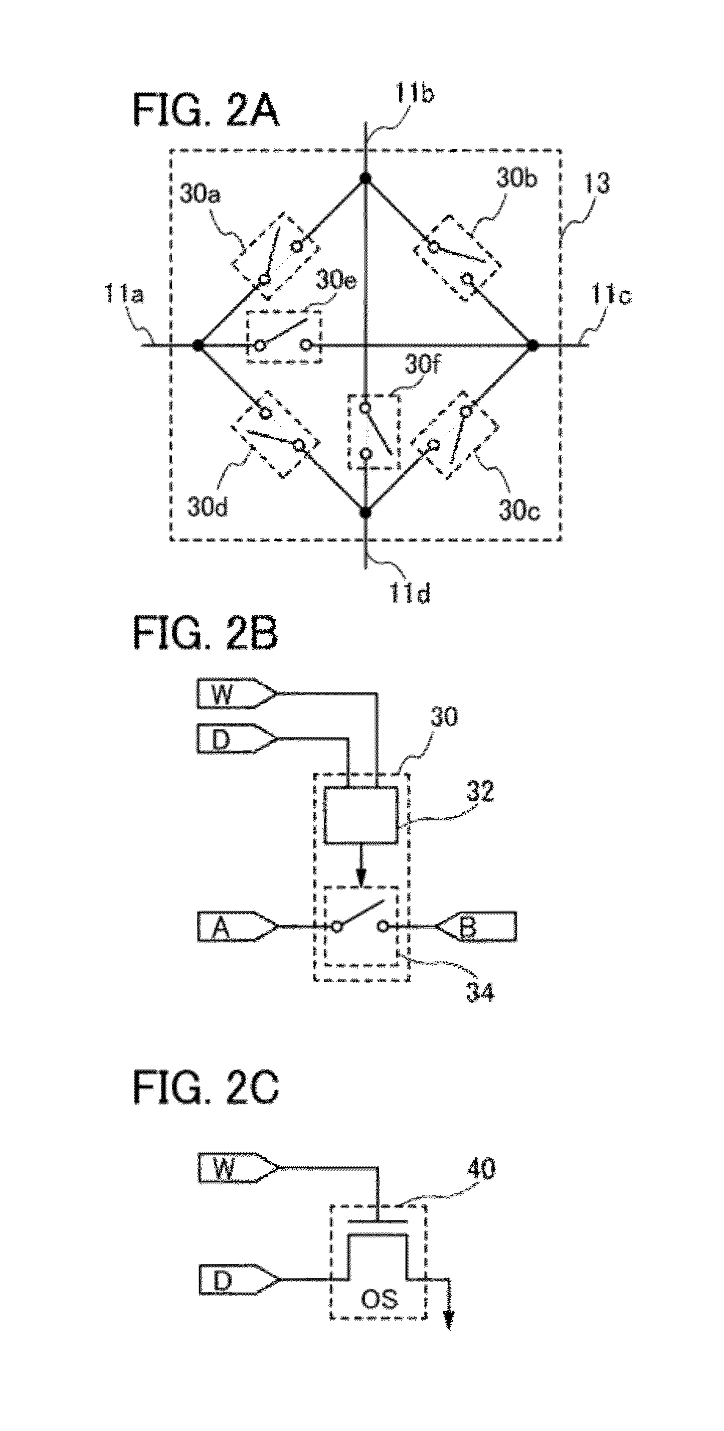
[0056]In this embodiment, a circuit structure of a programmable logic device according to an embodiment of the disclosed invention will be described with reference to FIGS. 1A and 1B, FIGS. 2A to 2C, FIGS. 3A to 3D, FIGS. 4A to 4C, and FIGS. 5A to 5C.
[0057]FIG. 1A shows a structure of a programmable logic device according to an embodiment of the disclosed invention. The programmable logic device includes a plurality of logic blocks 10 each including a plurality of logic circuits, a plurality of wirings 11 electrically connected to the plurality of logic blocks 10, and switch matrixes 12 each provided at an intersection of the plurality of wirings 11. The plurality of logic blocks 10 is preferably arranged in matrix as illustrated in FIG. 1A. At least one wiring 11 is provided between the logic blocks 10 and extends in the row direction or in the column direction. Further, each of the switch matrixes 12 is provided at the intersection of the plurality of wirings 11 extending in the r...
embodiment 2
[0108]In this embodiment, a method for manufacturing the programmable switch of the programmable logic device in Embodiment 1 will be described with reference to FIGS. 6A to 6D, FIGS. 7A and 7B, FIGS. 8A to 8C, and FIGS. 9A and 9B. A method for manufacturing the programmable switch including the transistor 110 and the transistor 112, which is illustrated in FIG. 3A, will be described as an example. Note that in FIGS. 6A to 6D, FIGS. 7A and 7B, FIGS. 8A to 8C, and FIGS. 9A and 9B, a cross-sectional view taken along line A-B corresponds to a cross-sectional view of a region where the transistor 110 including an oxide semiconductor film and the n-channel transistor 112 are formed, and a cross-sectional view taken along line C-D corresponds to a cross-sectional view of the node FG at which the one of the source electrode and the drain electrode of the transistor 110 including an oxide semiconductor film is connected to the gate electrode of the n-channel transistor 112.
[0109]First, as i...
embodiment 3
[0264]In this embodiment, the field-effect mobility of the transistor including an oxide semiconductor film, which is described in the above embodiments, is theoretically calculated, and the transistor characteristics are calculated from the field-effect mobility.
[0265]The actually measured field-effect mobility of an insulated gate transistor is lower than its theoretical mobility because of a variety of reasons; this phenomenon occurs not only in the case of using an oxide semiconductor. One of the reasons that reduce the mobility is a defect inside a semiconductor or a defect at an interface between the semiconductor and an insulating film. When a Levinson model is used, the field-effect mobility on the assumption that no defect exists inside the semiconductor can be calculated theoretically.
[0266]Assuming that a potential barrier (such as a grain boundary) exists in the semiconductor, the measured field-effect mobility μ can be expressed by the following Formula 2.
[0267][Formula...
PUM
 Abstract
Description
Claims
Application Information
 - R&D
- Intellectual Property
- Life Sciences
- Materials
- Tech Scout
- Unparalleled Data Quality
- Higher Quality Content
- 60% Fewer Hallucinations
Browse by: Latest US Patents, China's latest patents, Technical Efficacy Thesaurus, Application Domain, Technology Topic, Popular Technical Reports.
© 2025 PatSnap. All rights reserved.Legal|Privacy policy|Modern Slavery Act Transparency Statement|Sitemap|About US| Contact US: help@patsnap.com


