Solid-state image pickup apparatus signal processing method for a solid-state image pickup apparatus, and electronic apparatus
a solid-state image and pickup apparatus technology, applied in the direction of diodes, color television details, television systems, etc., can solve the problems of small reduced ad convertible input voltage range, and not only the dispersion of reset levels, so as to reduce the input voltage range within which the input voltage can be processed by the signal processing section, the effect of reducing the output amplitude of the pixel
- Summary
- Abstract
- Description
- Claims
- Application Information
AI Technical Summary
Benefits of technology
Problems solved by technology
Method used
Image
Examples
first embodiment
1. First Embodiment
1-1. System Configuration
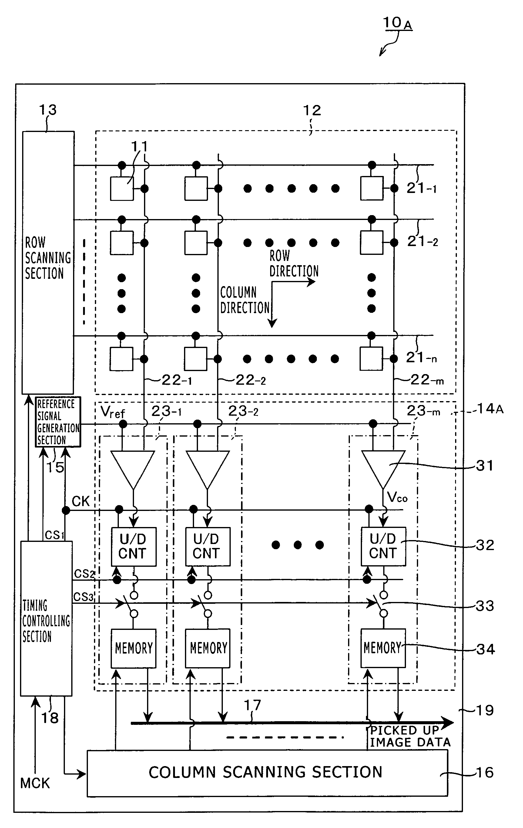
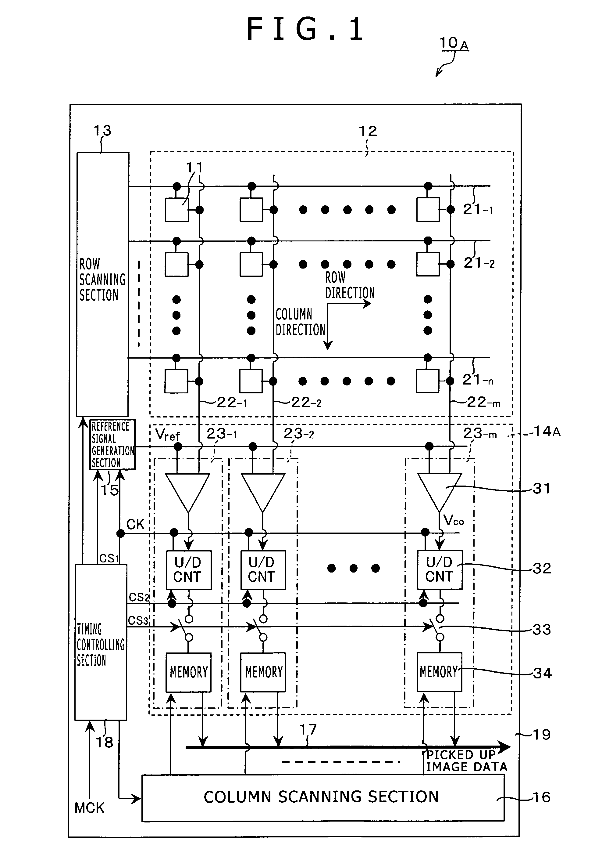
[0098]FIG. 1 shows a general configuration of a solid-state image pickup apparatus according to a first embodiment of the present invention, for example, a complementary metal oxide semiconductor (CMOS) image sensor which is a kind of X-Y address type solid-state image pickup apparatus. The CMOS image sensor is an image sensor produced applying a CMOS process or partially using a CMOS process.
[0099]Referring to FIG. 1, the CMOS image sensor 10A according to the present embodiment includes a pixel array section 12 having a plurality of unit pixels 11 disposed two-dimensionally in rows and columns, and peripheral driving and signal processing systems for driving the unit pixels 11 of the pixel array section 12. In the CMOS image sensor 10A shown in FIG. 1, as the peripheral driving and signal processing systems, for example, a row scanning section 13, a column processing section 14A, a reference signal generation section 15, a column scannin...
working example 3
[0210]FIG. 19 is a circuit diagram showing an example of a configuration of a comparator according to a working example 3 which includes a function for adjusting the internal reference voltages Vouti and Vrefi of the AD conversion circuit 23.
[0211]Referring to FIG. 19, the comparator 31C according to the working example 3 has a two-stage circuit structure including a preceding stage circuit section and a succeeding stage circuit section. The preceding stage circuit section has a circuit configuration same as that of the comparator 31A according to the working example 1, that is, has a circuit configuration of a comparison circuit section 81. It is to be noted that the preceding stage circuit section is not limited to that of a circuit configuration same as that of the comparator 31A according to the working example 1, but may have a circuit configuration same as that of the comparator 31B according to the working example 2.
[0212]On the other hand, the succeeding stage circuit sectio...
first driving example
[0216]Now, a first driving example of the comparator 31C according to the working example 3 which includes the storage circuit section 82 on the succeeding stage of the comparison circuit section 81 is described with reference to a timing waveform diagram of FIG. 20. In FIG. 20, timing waveforms of the control signals xΦR, xΦext and xΦR2, reference voltages Vrefi, Vouti are illustrated.
[0217]First, upon CDS driving, in the comparison circuit section 81, an initial voltage set by placement of the PMOS transistors 58 and 59 into a conducting state is retained as the internal reference voltages Vouti and Vrefi into the gate side of the NMOS transistors 51 and 52 under the control of the control signal xΦR. In the initialization state, NMOS transistor 823 of the storage circuit section 82 on the succeeding stage is placed into a conducting state under the control of the control signal xΦR2.
[0218]When the NMOS transistor 823 in the storage circuit section 82 on the succeeding stage is pl...
PUM
 Abstract
Description
Claims
Application Information
 - R&D
- Intellectual Property
- Life Sciences
- Materials
- Tech Scout
- Unparalleled Data Quality
- Higher Quality Content
- 60% Fewer Hallucinations
Browse by: Latest US Patents, China's latest patents, Technical Efficacy Thesaurus, Application Domain, Technology Topic, Popular Technical Reports.
© 2025 PatSnap. All rights reserved.Legal|Privacy policy|Modern Slavery Act Transparency Statement|Sitemap|About US| Contact US: help@patsnap.com


