
Power conversion apparatus, discharge lamp ballast and headlight ballast

a technology of power conversion apparatus and discharge lamp, which is applied in the direction of electric variable regulation, process and machine control, instruments, etc., can solve the problems of easy disturbance, power loss, and sensor signal reduction, and achieve the effect of securing feedback control stability and suppressing output fluctuation

Inactive Publication Date: 2013-11-05
PANASONIC CORP
View PDF23 Cites 4 Cited by
  • Summary
  • Abstract
  • Description
  • Claims
  • Application Information

AI Technical Summary

Benefits of technology

The invention aims to reduce fluctuations in output while maintaining stability in a continuous mode. This is achieved by using a simulation signal from the magnetic device to control the feedback.

Problems solved by technology

However, if the resistor is used as the current sensor, power loss occurs.
If a low resistor is used as the current sensor, power loss can be reduced, but a sensor signal is reduced and is easily affected by disturbance (noise).
However, in a continuous mode of the second prior art, if input voltage or load voltage fluctuates slightly or the off timing of the switching device is slightly shifted by noise or the like, the output power can be fluctuated greatly.
Specifically, when the switching device is turned off, if the output power increases slightly, an inclination of an electric current through the secondary winding becomes large.
Similarly, increase in output causes great fluctuation.
For this reason, if the gain of the feedback control is increased, the response speed can be increased, but the feedback control stability becomes impaired.

Method used


Image

  • Power conversion apparatus, discharge lamp ballast and headlight ballast
  • Power conversion apparatus, discharge lamp ballast and headlight ballast
  • Power conversion apparatus, discharge lamp ballast and headlight ballast

Examples


first embodiment

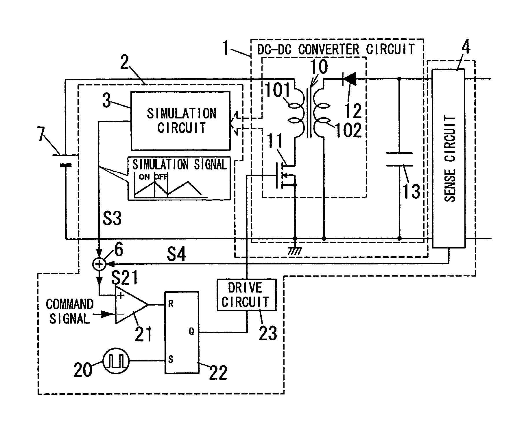
[0054]FIG. 7 shows power conversion apparatus in accordance with a first embodiment of the present invention. The power conversion apparatus in the first embodiment has the basic configuration of FIG. 1 and further includes an error amplifier circuit 24. For the purpose of clarity, like kind elements are assigned the same reference numerals as depicted in FIG. 1.

[0055]The error amplifier circuit 24 is configured, according to an output command from the outside, to detect output voltage and output current of the DC-DC converter circuit 1 to produce a command signal of on-period by error calculation of the output voltage and output current. The output voltage of the DC-DC converter circuit 1 is detected from the junction of the diode 12 and the capacitor 13, for example, through a voltage divider (not shown). The output current of the DC-DC converter circuit 1 is obtained from a sense circuit 4 to be hereinafter described. The command signal is supplied to the inverting input of the c...

second embodiment

[0068]FIG. 9 shows power conversion apparatus in accordance with a second embodiment of the present invention. The power conversion apparatus in the second embodiment has the basic configuration of FIG. 1. For the purpose of clarity, like kind elements are assigned the same reference numerals as depicted in FIGS. 1 and 7.

[0069]The power conversion apparatus of the second embodiment is characterized by a sense circuit 4 different from that of the first embodiment. That is, the circuit 4 is configured to produce a signal S4 which corresponds to the output (output voltage) of the DC-DC converter circuit 1 and is superposed on a simulation signal S3 at the junction the resistor 34 and the capacitor 30 to form a superposed signal S21. Since the output of the DC-DC converter circuit 1 is negative voltage, the sense circuit 1 has, but not limited to, resistors 41-43 and an operational amplifier 44 that constitute an inverting amplifier. The resistor 41 has first and second ends, and the fi...

third embodiment

[0073]FIG. 10 shows power conversion apparatus in accordance with a third embodiment of the present invention. The power conversion apparatus in the third embodiment has the basic configuration of FIG. 1. For the purpose of clarity, like kind elements are assigned the same reference numerals as depicted in FIGS. 1 and 7.

[0074]The power conversion apparatus in the third embodiment is characterized by a sense circuit 4 different from the first embodiment's one. The transformer 10 also has an auxiliary winding 103 at the secondary side in addition to primary and secondary windings 101 and 102. The auxiliary winding 103 has first and second ends, and the polarity of the second end of the auxiliary winding 103 is the same as that of each second end of the primary and secondary windings 101 and 102. The first and second ends of the auxiliary winding 103 are connected with the first end of the resistor 34 and the second end of the capacitor 30, respectively.

[0075]The sense circuit 4 in the...


PUM


Abstract

Power conversion apparatus includes a converter circuit, a control circuit, a simulation circuit and a sense circuit. The converter circuit includes a magnetic device for power conversion and a switching device, and is configured to convert power from a power supply into direct current power. The control circuit is configured to supply the converter circuit with a high frequency signal for turning the switching device on and off. The simulation circuit is configured to produce a simulation signal that simulates state or change of magnetic flux of the magnetic device. The sense circuit is configured to produce a signal which corresponds to at least one of the input and output of the converter circuit and is superposed on the simulation signal to form a superposed signal. The control circuit defines an on-period of the high frequency signal based on the superposed signal.

Description

TECHNICAL FIELD[0001]The invention relates generally to power conversion apparatus, and more particularly to power conversion apparatus comprising a magnetic element for power conversion, a discharge lamp ballast comprising the power conversion apparatus and a headlight (headlamp) ballast comprising the power conversion apparatus.BACKGROUND ART[0002]Japanese Patent Application Publication No. 2000-340385 describes a ballast for a discharge lamp (e.g., a high intensity discharge (HID) lamp). The ballast (hereinafter referred to as a “first prior art”) includes a DC-DC converter circuit, an inverter circuit, a start circuit and an output control circuit, and is especially characterized by the DC-DC converter circuit and the output control circuit.[0003]The DC-DC converter circuit is a flyback converter configured to convert voltage from a DC (direct current) power supply into specified voltage, and has a transformer with primary and secondary windings, a switching device, a diode and ...

Claims


Application Information

Patent Timeline
Patent Type & Authority Patents(United States)
IPC IPC(8): H05B37/02H02M3/335
CPCH02M3/33507H05B41/2886Y02B20/202Y02B20/00
Inventor NAKAMURA, TOSHIAKI
Owner PANASONIC CORP
Learn More