
Systems and methods for path-based management of virtual servers in storage network environments

Active Publication Date: 2013-10-15
NETWORK APPLIANCE INC
View PDF27 Cites 119 Cited by
  • Summary
  • Abstract
  • Description
  • Claims
  • Application Information

AI Technical Summary

Benefits of technology

This patent describes a system and method for managing access paths and state changes in virtual machine environments to maximize server consolidation and minimize storage costs. The system uses logical access paths to monitor the performance and utilization of components in the storage network, without using host agents. This allows for real-time and historical monitoring of the VMs, maximizing service levels and performance. Overall, the patent introduces a new approach for managing virtualized storage networks that optimizes server consolidation and storage utilization.

Problems solved by technology

Furthermore, these storage network environments undergo frequent change and growth as, for example, hosts are added to the storage network.
This large size and rate of growth of SANs leads to huge added complexity.
This complexity, which is compounded by the heterogeneity of the different SAN devices, leads to high risk and inefficiency.
Changes to the SAN (which need to happen often due to the natural growth of the SAN) take a long time to complete by groups of SAN managers or administrators, and are error-prone.
The complexity of storage network environments has recently been further complicated by the increasing adoption of virtual servers or virtual machines (VMs) as hosts within storage network environments.
First, server hardware performance continues to increase faster than the ability of most applications to use it.
As a result, many organizations are barely getting above 20 percent server central processing unit (CPU) utilization, a large inefficiency in processor utilization which can be addressed by using virtual servers, or virtual machine, technology, within the physical servers or hosts.
Second, the market adoption of Microsoft™ Windows™ servers running on x86 CPUs has dramatically driven down the cost of computing.
However, most system administrators will not run multiple applications on a single system image because they fear that conflicts e.g. DLL conflicts and other incompatibilities will cause systems to crash.
The result has been one physical server with one operating system deployed for each application, leading to a proliferation of underutilized servers in the data center.
Third, many companies are undergoing data center consolidation efforts to control the massive sprawl of underutilized server capacity that is consuming space and power in today's increasingly expensive data centers.
Each operating system image and server also requires costly, labor-intensive operating system (OS) patch maintenance and updates to the corresponding physical infrastructure.
As part of these consolidation efforts, data center teams must choose between re-hosting these applications on even more powerful virtual servers (exacerbating the underutilization problem) or leaving them on old, unsupported physical server hardware.
However, with the benefit of virtual machine technology in storage network environments come storage network environment problems that need to be addressed.
There is a challenge in terms of determining how to effectively manage the large number of server images or virtual servers on each physical server in a storage network environment.
Unless the SAN administrator systemically goes back to delete these storage volumes, the storage space is consumed.
This type of VM sprawl has the potential to increase storage consumption by an order of magnitude, thereby reducing the benefit of having virtual servers deployed in storage network environments.
In addition, it is even more difficult to detect network state changes, which occur frequently, within a storage network environment with virtual servers than in a storage network environment with only physical servers.
For instance, a failure of a storage area network switch may eliminate an access path between two components on the network thereby disrupting the corresponding data flow to many virtual servers instead of just one physical server.
Currently, there are no adequate technological solutions to assist SAN or VM administrators in managing changing storage network environments with virtual machine components e.g. virtual servers.
In particular, SAN administrators cannot quickly and dynamically discover all relevant changes in SAN state, particularly in relation to application data requirements involving virtual servers.
For instance, a server outage is always a serious event in a storage network environment.
In a virtualized storage network environment, however, the impact is an order of magnitude higher simply because for each virtual server outage, many more applications are affected.
Until recently, no software or hardware applications were available to manage virtualized storage network environments.
Furthermore, host agents on a physical server are very difficult to manage and / or maintain, and are widely considered undesirable for large SANs in which scalability may be important.

Method used


Image

  • Systems and methods for path-based management of virtual servers in storage network environments
  • Systems and methods for path-based management of virtual servers in storage network environments
  • Systems and methods for path-based management of virtual servers in storage network environments

Examples


exemplary embodiment 1100

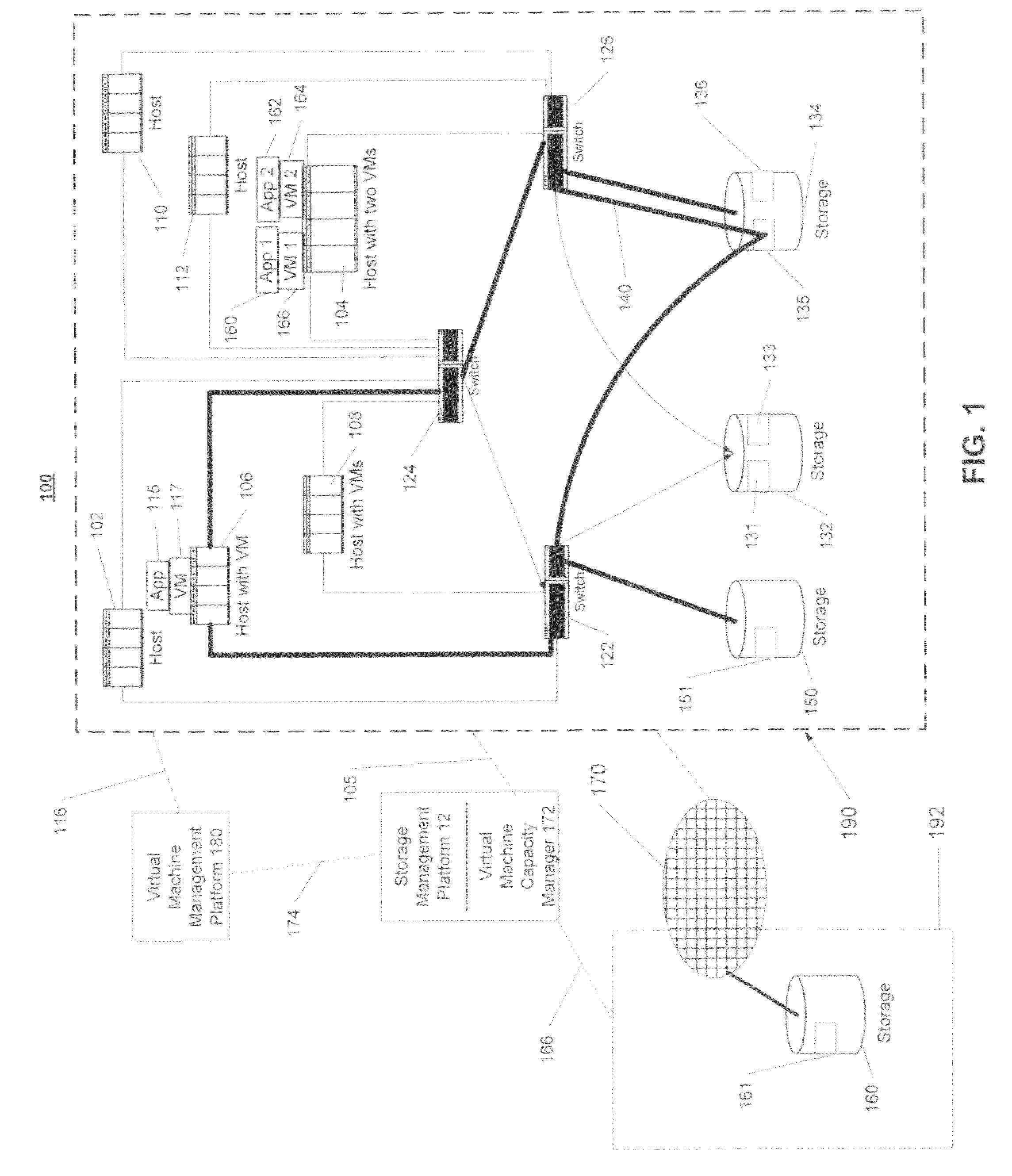
[0145]FIG. 11 illustrates an exemplary embodiment 1100 of the virtual machine capacity management process 1000 of FIG. 10C in response to an occurrence of a change event, such as virtual machine change event 1006 of FIG. 10C. The capacity management process 1000 first determines, at step 1102, the nature of the virtual machine change event 1006 in order to formulate the appropriate actions to such an event. The process 1000 then determines, at steps 1104 and 1106, one or more applications and resources in a data network that may be affected by the virtual machine change event. At step 1108, the process 1000 reserves the selected virtual machine resources, of appropriate types and tiers, in a reservation system corresponding each of the identified applications. The reservation system may be configured to prevent double reservation of the virtual machine resources by parallel change processes. Furthermore, at step 1110, process 1000 executes the allocation virtual machine change event...

exemplary embodiment 1200

[0149]FIG. 12 illustrates an exemplary embodiment 1200 of the process 1000 at the reconciliation stage 1006 of FIG. 10C. The virtual machine capacity manager 172 of FIG. 1 first (step 1208) performs the virtual machine capacity assessment process described above in FIG. 11. Process 1000 proceeds by comparing the current virtual machine status generated at step 1208 of FIG. 12 with a projected status of virtual machine resource association generated from the projection stage 1002 of FIG. 10C. In one embodiment, the comparison is performed in an application-centric mariner. For example, the association value that tracks each type and tier of allocated and reserved virtual machine resource corresponding to an application may be compared, at step 1210, to the estimated level of capacity stored in an expected-resource requirement policy for that application. This comparison thus allows a user to evaluate virtual machine capacity association from an application-oriented perspective. In an...


PUM


Abstract

Systems and methods for analyzing the service and performance levels associated with virtual machines in a storage network environment for compliance with a resource capacity policy are provided. Component configuration and connectivity information from components in the network environment is collected without using host agents on the virtual machines. Access paths defining end-to-end access relationships between an application on a virtual machine and storage data objects associated with the virtual machine in the network environment are derived. Access paths comprise sequences of components configured to enable information flow between an application residing on a virtual machine and a data object on a respective storage device. Access path resource consumption is computed and virtual machines with resource consumptions that violate the resource capacity policy are identified.

Description

CROSS-REFERENCE TO RELATED PATENT APPLICATIONS[0001]This application is a continuation-in-part of U.S. patent application Ser. No. 10 / 693,632 filed on Oct. 23, 2003, and claims the benefit of U.S. Provisional Application No. 60 / 993,147 filed Sep. 10, 2007, and U.S. Provisional Application No. 60 / 993,187 filed Sep. 10, 2007, the contents of which are hereby incorporated herein by reference in their entirety.FIELD OF THE INVENTION[0002]The systems and methods generally relate to the field of storage capacity management in storage environments with virtual machines or virtual servers.BACKGROUND OF THE INVENTION[0003]A SAN or storage area network, sometimes called a storage network environment, is a network dedicated to enabling multiple applications on multiple hosts to access, i.e., read and write, data stored in consolidated shared storage infrastructures. A SAN consists of SAN devices, for example, different types of switches, which are interlinked, and is based on a number of possi...

Claims


Application Information

Patent Timeline
IPC IPC(8): G06F15/173
CPCH04L67/1097H04L69/329H04L63/101G06F11/3495G06F11/3442G06F2201/815H04L67/63Y10S707/99931H04L9/40G06F9/45545G06F9/5016
Inventor YAHALOM, RAPHAELLEVY, ASSAFKESSEL, OMRIALON, ROEEYAAKOBI, MICHAEL
Owner NETWORK APPLIANCE INC
Learn More