
Internal combustion engine exhaust gas control apparatus and abnormality determining method thereof

Active Publication Date: 2013-10-15
TOYOTA JIDOSHA KK
View PDF15 Cites 4 Cited by
  • Summary
  • Abstract
  • Description
  • Claims
  • Application Information

AI Technical Summary

Benefits of technology

[0015]Also, in the exhaust gas control apparatus described above, the second estimating portion may estimate an amount of oxygen released from the catalyst per unit time based on an engine operating state, during the period of time between the point in time at which the forced rich control starts and the point in time at which the output of the oxygen sensor makes a rich reversal, and estimate the oxygen release amount by integrating the estimated released oxygen amount over the period of time. Further, the third estimating portion may estimate an amount of oxygen stored in the catalyst per unit time based on the engine operating state, during the period of time between the point in time at which the forced lean control starts and the point in time at which the output of the oxygen sensor makes a lean reversal, and estimate the oxygen storage amount by integrating the estimated stored oxygen amount over the period of time. As a result, the oxygen release amount and the oxygen storage amount are able to be accurately estimated.
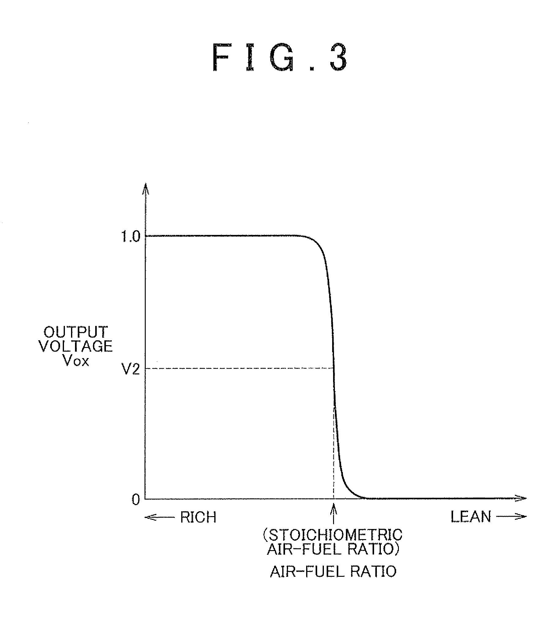
[0017]When the oxygen sensor continues to output a value corresponding to an air-fuel ratio that is leaner than the stoichiometric air-fuel ratio for a predetermined period of time, the amount of oxygen stored in the catalyst is the maximum amount. Accordingly, with the structure described above, it is possible to easily and accurately estimate that the amount of oxygen stored in the catalyst is the maximum amount. Incidentally, a predetermined period of time may be set through simulation or testing using the oxygen sensor and the catalyst.
[0019]According to this structure, it is possible to easily estimate that the amount of oxygen stored in the catalyst is the minimum amount. Also, the oxygen release amount and the oxygen storage amount may be set in the following manner, for example. That is, when the oxygen sensor continues to output a value corresponding to an air-fuel ratio that is leaner than the stoichiometric air-fuel ratio for a predetermined period of time, the amount of oxygen stored in the catalyst is determined to be the maximum amount, and the oxygen release amount starts to be estimated. The oxygen release amount continues to be estimated until the output of the oxygen sensor makes a rich reversal. Then when the output of the oxygen sensor makes a rich reversal, the amount of oxygen stored in the catalyst is determined to be the minimum amount, and the oxygen storage amount starts to be estimated. The oxygen storage amount continues to be estimated until the output of the oxygen sensor makes a lean reversal. Alternately estimating the oxygen release amount and estimating the oxygen storage amount in this way makes it possible to shorten the time that it takes to estimate the total oxygen release amount and the total oxygen storage amount.
[0022]Regarding this, with the structure described above, if a delay abnormality occurs in the lean reversal of the output of the oxygen sensor, it is able to be accurately ascertained by estimating the response delay time of the lean reversal of the oxygen sensor while fuel cut control is being executed. Also, by taking the response delay time into account when estimating the oxygen storage amount prior to making the abnormality determination of the oxygen sensor, it is possible to precisely estimate the oxygen storage amount even if there is a response delay abnormality in the lean reversal of the output of the oxygen sensor. Thus, even if there is a response delay abnormality of a similar degree in both the rich reversal and the lean reversal of the output of the oxygen sensor, it is able to be accurately ascertained.
[0026]The measured lean continuation time may be regarded as the oxygen release amount of the catalyst by controlling a target air-fuel ratio such that the amount of oxygen released from the catalyst per unit time becomes constant while the forced rich control is being executed. Also, the measured rich continuation time may be regarded as the oxygen storage amount of the catalyst by controlling a target air-fuel ratio such that the amount of oxygen stored in the catalyst per unit time becomes constant while the forced lean control is being executed. Thus, according to the exhaust gas control apparatus and the abnormality determining method thereof described above, it is possible accurately ascertain that there is a response delay in one of the rich reversal or the lean reversal of the output of the oxygen sensor, similar to the oxygen control apparatus and the abnormality determining method thereof that determine a response delay abnormality in an oxygen sensor by estimating the oxygen release amount and the oxygen storage amount described above.

Problems solved by technology

However, if there is a response delay in the rich reversal of the output of the oxygen sensor, the output of the oxygen sensor will make the rich reversal at a timing that is later than the timing at which the catalyst actually becomes no longer able to release oxygen.

Method used


Image

  • Internal combustion engine exhaust gas control apparatus and abnormality determining method thereof
  • Internal combustion engine exhaust gas control apparatus and abnormality determining method thereof
  • Internal combustion engine exhaust gas control apparatus and abnormality determining method thereof

Examples


Embodiment Construction

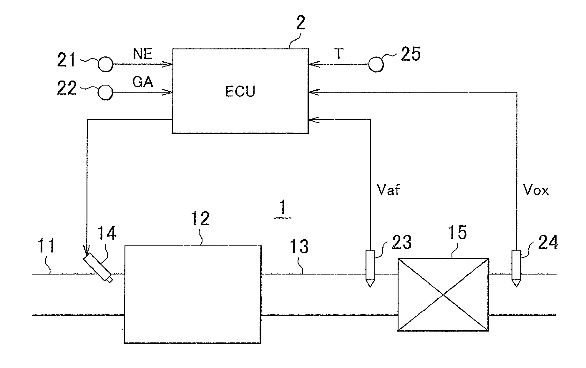
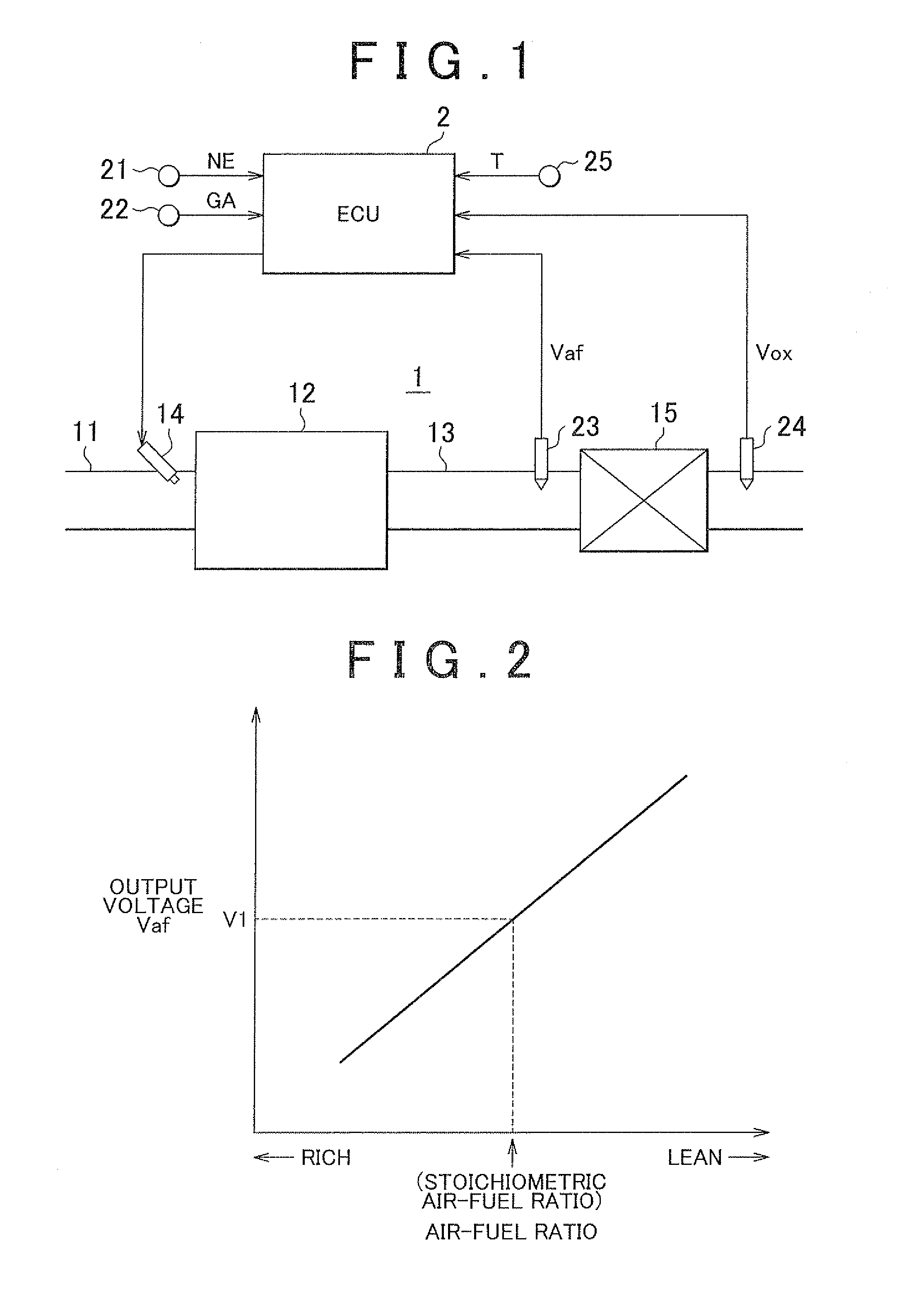
[0049]Hereinafter, a first example embodiment in which an exhaust gas control apparatus of an internal combustion engine of the invention is embodied as an exhaust gas control apparatus for port injection type gasoline engine (hereinafter, referred to as “internal combustion engine 1”) that is mounted in a vehicle will be described in detail with reference to FIGS. 1 to 7.

[0050]FIG. 1 is a schematic diagram of the general configuration of the internal combustion engine 1 and an electronic control unit (ECU) 2 that controls the internal combustion engine 1. As shown in FIG. 1, the internal combustion engine 1 includes an intake passage 11, a combustion chamber 12, and an exhaust passage 13. The intake passage 11 is a passage that supplies air to the combustion chamber 12. Also, a fuel injection valve 14 that injects fuel into an intake port of the intake passage 11 is provided in the intake passage 11. Air supplied through a throttle valve in the intake passage 11 mixes with fuel inj...


PUM


Abstract

When it is estimated that an amount of oxygen stored in the catalyst is a maximum amount, an electronic control unit executes forced rich control and estimates a maximum oxygen release amount during a period between the start of this control and a rich reversal of an output of the oxygen sensor, based on this period of time. When it is estimated that the amount of oxygen stored in the catalyst is a minimum amount, the electronic control unit executes forced lean control and estimates a maximum oxygen storage amount during a period between the start of this control and a lean reversal of the output of the oxygen sensor, based on this period of time. If the absolute value of a difference between the maximum oxygen release amount and the maximum oxygen storage amount is equal to or greater than a predetermined value, an exhaust gas control apparatus and a method for determining an abnormality thereof determine that there is a response delay.

Description

INCORPORATION BY REFERENCE[0001]The disclosure of Japanese Patent Application No. 2010-062844 filed on Mar. 18, 2010 including the specification, drawings and abstract is incorporated herein by reference in its entirety.BACKGROUND OF THE INVENTION[0002]1. Field of the Invention[0003]The invention relates to an exhaust gas control apparatus of an internal combustion engine, that includes a catalyst that is provided in an exhaust passage of an internal combustion engine and has the ability to store oxygen, and an oxygen sensor that is provided on the exhaust gas downstream side of the catalyst in the exhaust passage and outputs a signal indicative of an air-fuel ratio of exhaust gas. The invention also relates to a method for determining an abnormality in this exhaust gas control apparatus.[0004]2. Description of the Related Art[0005]An exhaust gas control apparatus of an internal combustion engine purifies carbon monoxide (CO), hydrocarbons (HC), and oxides of nitrogen (NOx) in exhau...

Claims


Application Information

Patent Timeline
Patent Type & Authority Patents(United States)
IPC IPC(8): F01N3/00
CPCF02D41/222F02D41/1454F02D2200/0816Y02T10/40
Inventor SATO, MAKOTO
Owner TOYOTA JIDOSHA KK
Learn More