
Adjustable angle inlet for turbojet engines

a turbojet engine and angle adjustment technology, applied in the field of aeronautics, can solve the problems of high angle of attack flight, high angle of attack required, affecting the airflow around the wing of the airplane, and affecting the airflow around other aircraft components, so as to prevent engine compressor stalls or allay the effect of stalling

Inactive Publication Date: 2013-10-01
SHAMMOH ALI A A J
View PDF16 Cites 16 Cited by
  • Summary
  • Abstract
  • Description
  • Claims
  • Application Information

AI Technical Summary

Benefits of technology

The adjustable angle inlet is a device that helps turbojet engines compensate for changes in the angle at which they are attached to the jet aircraft. This prevents engine compressor stalls caused by airflow interruptions. The adjustable angle inlet can be used with any jet engine, but it is particularly suitable for engines mounted on the rear of the jet aircraft. This configuration ensures an aerodynamic "clean" engine nacelle, with minimal interference from other structures in front of the inlet.

Problems solved by technology

However, high angle of attack flight can occur at higher speeds as well, particularly when maneuvering at relatively high airframe aerodynamic loads (“high G loading”).
It will be seen that the relatively high angle of attack required for such slow speed flight not only affects the airflow around the wing of the airplane, but also affects the airflow around other aircraft components as well.
Although not a frequent occurrence, from time to time a turbojet-powered aircraft will undergo sufficient disruption of the incoming air that the engine can no longer maintain proper flow through the engine.
This results in what is known as a “compressor stall,” in which at least some portion of the blades in the compressor section of the engine become stalled, i.e., they no longer accelerate the airflow through the compressor.
This results in reduction or complete loss of power in the engine.
Accordingly, a great deal of effort has gone into alleviating or preventing compressor stalls.
High angles of attack are unavoidable, as a jet airplane is required to operate at high angles of attack at the beginning and end of its flight.
However, little, if any, prior work has been done toward providing smooth airflow into the engine inlet by adjusting the angle of the nacelle inlet as the aircraft angle of attack changes.

Method used


Image

  • Adjustable angle inlet for turbojet engines
  • Adjustable angle inlet for turbojet engines
  • Adjustable angle inlet for turbojet engines

Examples


Embodiment Construction

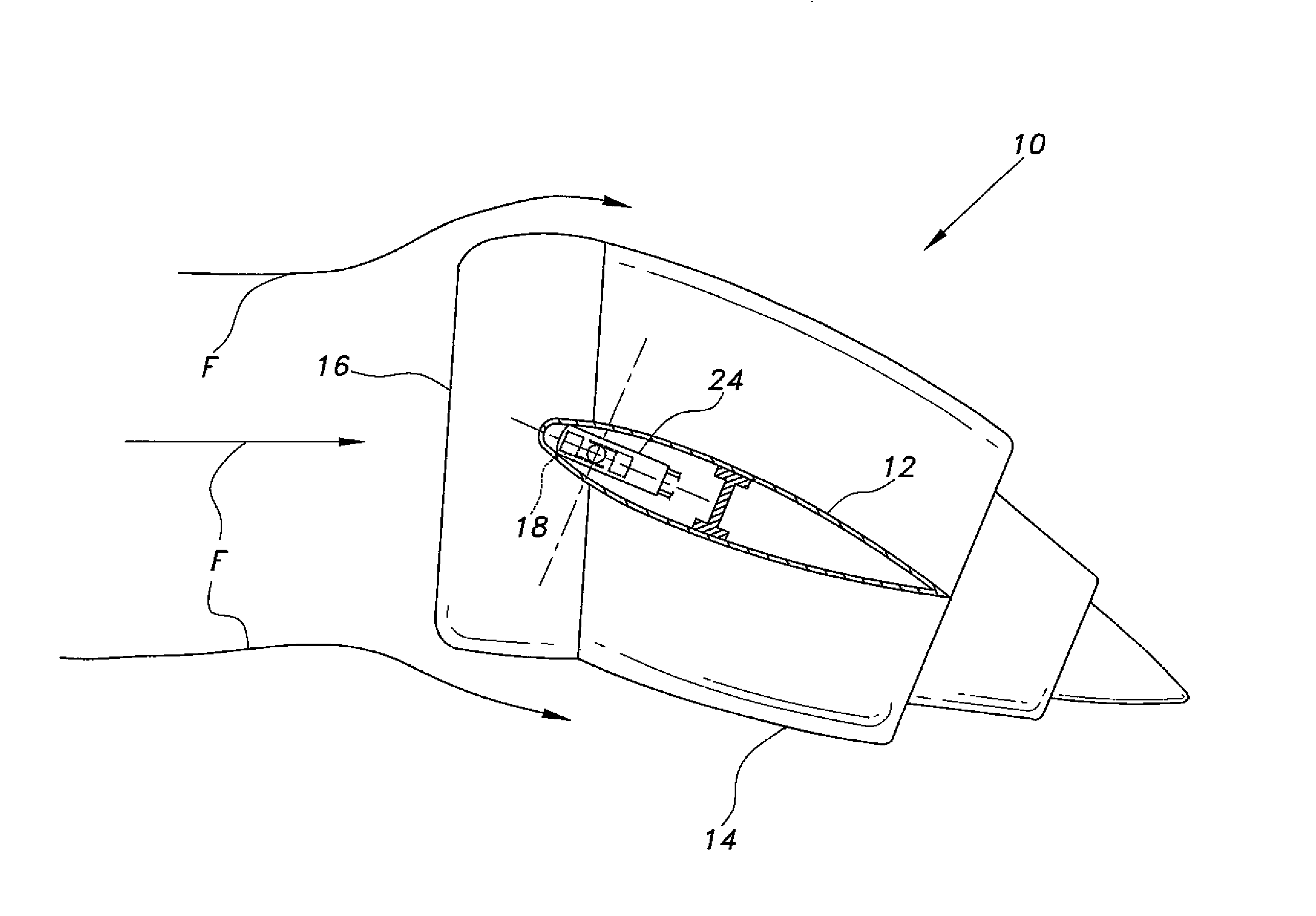
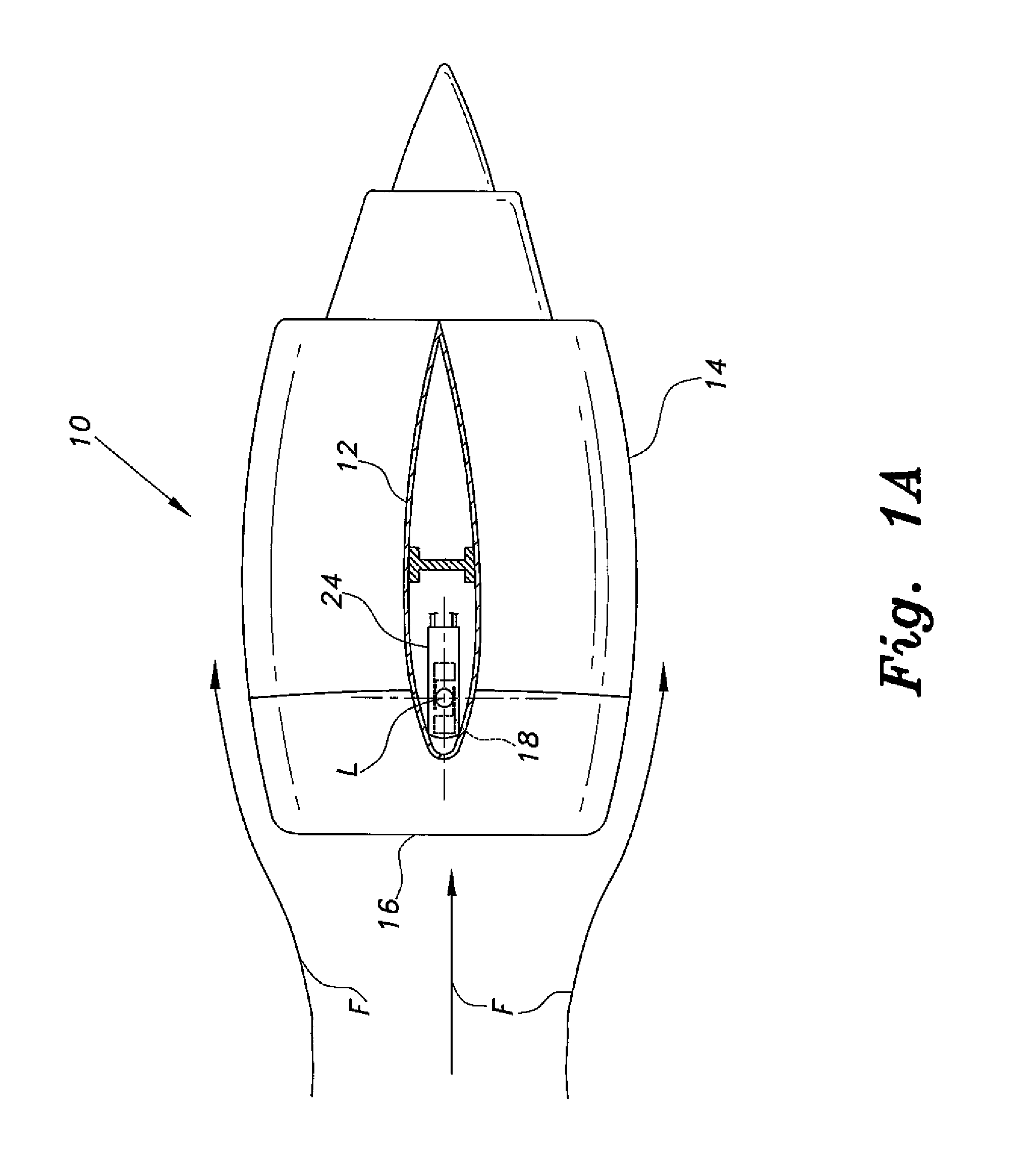
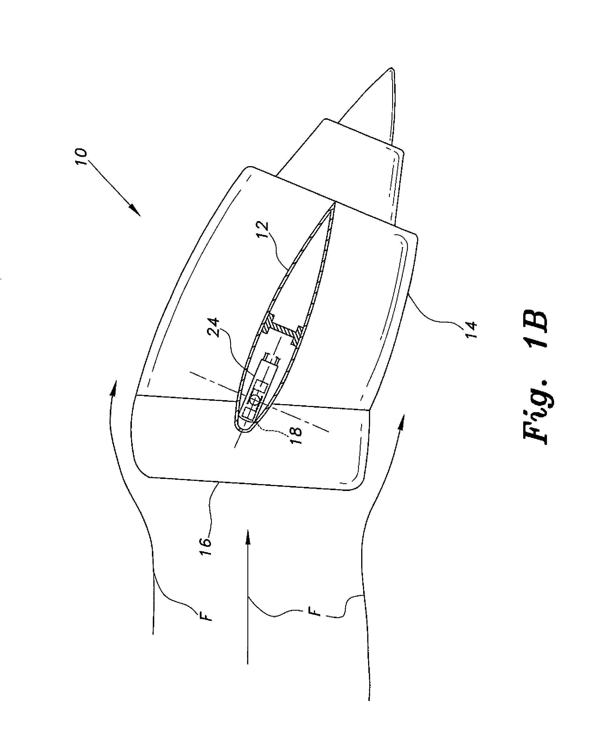
[0016]The adjustable angle inlet for turbojet engines allows the nacelle inlet angles to be adjusted for varying angles of attack in an aircraft having externally mounted engine nacelles, e.g., extending laterally from pylons mounted on the rear fuselage of the airframe. This provides for optimum inlet airflow during high angle of attack maneuvers, such as takeoffs, landings, and high-G maneuvers at higher speeds. The adjustable angle inlet aligns the incoming airflow with the compressor section of the turbojet engine, thereby alleviating or precluding compressor stall of the engine.

[0017]FIG. 1A of the drawings is a left side elevation view of the of the right side turbojet engine nacelle 10, showing the nacelle as it would extend laterally from the right side engine mount pylon 12 (the pylon is shown in section in FIG. 1A). The nacelle 10 comprises a main portion 14 immovably affixed to the pylon 12, and the adjustable angle inlet 16 extends forward of the main nacelle portion 14....


PUM


Abstract

The adjustable angle inlet for turbojet engines provides for the adjustment of the nacelle inlet as the angle of attack of the aircraft changes. The adjustable inlet system thus assures that the nacelle inlet is always oriented directly into the relative wind as the angle of attack of the aircraft changes, e.g., during takeoff, landing, and high-G maneuvers where the aircraft reaches relatively high angles of attack. The adjustable angle inlet is adaptable to most turbojet-powered airplanes, but is particularly well suited for use with aircraft having their engines mounted on lateral pylons on the rear of the fuselage. The system operates according to signals received from an angle of attack sensor. The sensor controls an actuator, which rotates a shaft that is connected to the pivotally mounted inlet of the engine nacelle.

Description

BACKGROUND OF THE INVENTION[0001]1. Field of the Invention[0002]The present invention relates generally to aeronautics, and particularly to an adjustable angle inlet for turbojet engines permitting the inlet portion of the engine cowling or nacelle to be adjusted according to the angle of attack of the aircraft.[0003]2. Description of the Related Art[0004]All aircraft that are dependent upon dynamic lift to maintain flight, e.g., fixed wing airplanes, helicopters, etc., generate that lift according to the angle of attack of the airfoil (wing or rotor blade) relative to the airflow over and around that airfoil. The amount of lift generated by an airfoil is proportional to the speed of the airfoil through the air and the angle of attack throughout normal flight attitudes, i.e., the angle of the airfoil relative to the angle of the approaching airflow. Thus, an airplane flying at relatively low speed must fly at a relatively high angle of attack to generate the required lifting force. ...

Claims


Application Information

Patent Timeline
IPC IPC(8): B64D33/02
CPCF02C7/04B64D2033/0226Y10T137/0536
Inventor SHAMMOH, ALI A. A. J.
Owner SHAMMOH ALI A A J
Learn More