System and method for autonomous vehicle localization

Active Publication Date: 2010-01-28
MTD PRODUCTS
View PDF29 Cites 31 Cited by
  • Summary
  • Abstract
  • Description
  • Claims
  • Application Information

AI Technical Summary

Benefits of technology

[0004]In a further form, the system utilizes stationary sonic receivers on both the mobile robot and beacons to improve the results obtained from the time of flight information. By analyzing the signals obtained from the stationary receivers the mobile robot can more accurately calculate the time of flight of the sonic signal by adjusting for various environmental conditions such as temperature, wind, and air turbulence.
[0005]In a still further form, the electromagnetic receiver on the mobile robot is an array of individual electromagnetic receivers allowing for a much more accurate determination as to the angle of receipt of the electromagnetic signal. The results from multiple individual receivers can be combined to reduce error and produce a result more accurate than possible when using a single receiver alone.
[0007]In yet another form, the mobile robot includes an inclinometer which provides information regarding the deviation of the mobile robot from a specified axis. This allows the mobile robot to compensate for changes in the terrain which could produce inaccuracies in the time of flight and angular reception measurements. As the mobile robot pitches and rolls the distance from the top of the communications tower to a beacon is different than the distance from the base of the mobile robot to a beacon. Since the height of the communications tower is known the deviation information provided by the inclinometer allows for the correction of these distances.
[0008]According to a still further form, the beacons can replicate various aspects of the sonic signal in the electromagnetic transmission rather than simply broadcasting an electromagnetic signal upon the receipt of a sonic signal. This allows the mobile robot to receive the replicated signal and analyze the signal to make determinations about the medium in which the sonic signal traveled as well as its reliability.
[0009]The sonic transmitter is preferably an array of individual sonic transmitters. These sonic transmitters can be individually controlled. By varying the phase of the individually broadcast signals the mobile robot can create constructive and destructive interference within the sonic signal. This allows the range to be extended in the case of constructive interference or for dead spots to be created to prevent the reception of the sonic signal by a particular beacon.

Problems solved by technology

If one of the beacons in these systems becomes unreachable they can no longer function.
Also the systems in the prior art do not take full advantage of encoding useful information into the signals, calculating the impact of changes in terrain, nor do they adequately compensate for varying environmental conditions and their effect upon a calculated position.

Method used


Image

  • System and method for autonomous vehicle localization
  • System and method for autonomous vehicle localization
  • System and method for autonomous vehicle localization

Examples


Embodiment Construction

[0014]For the purposes of promoting an understanding of the principles of the invention, reference will now be made to the embodiments illustrated in the drawings and specific language will be used to describe the same. It will nevertheless be understood that no limitation of the scope of the invention is thereby intended. Any alterations and further modifications in the described embodiments, and any further applications of the principles of the invention as described herein are contemplated as would normally occur to one skilled in the art to which the invention relates.

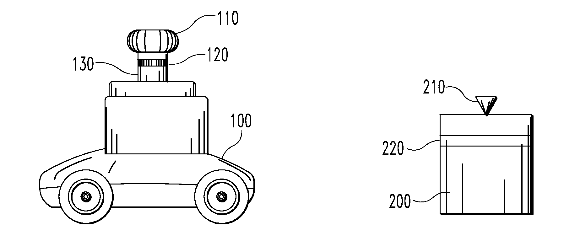
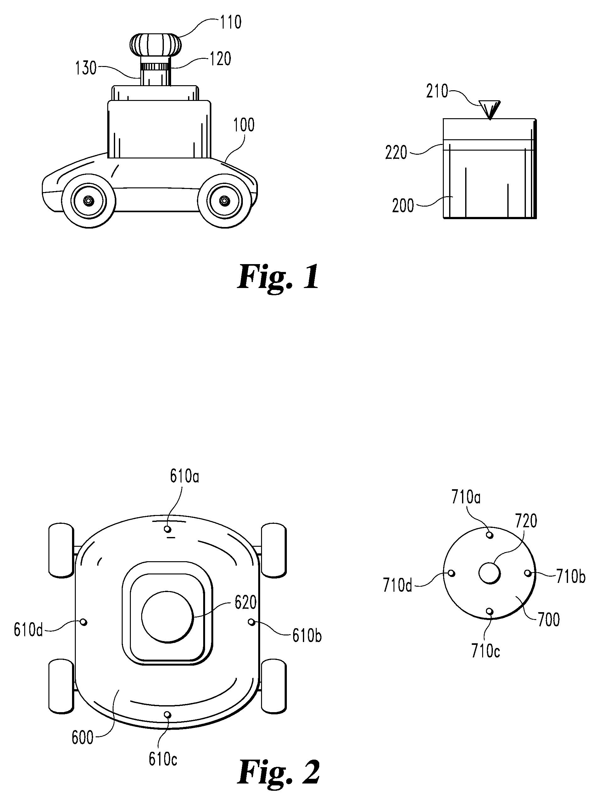
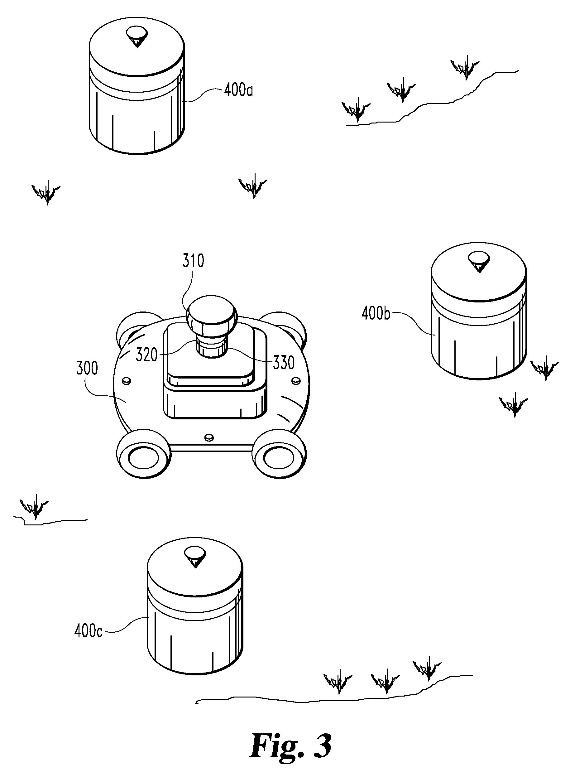
[0015]The illustrative embodiment of the present invention will be described with reference to FIG. 1. The autonomous vehicle includes a mobile robot 100 which is free to navigate its space and perform assigned tasks, such as, but in no way limited to, sorting boxes, picking merchandise, vacuuming a floor, or mowing a lawn. The mobile robot 100 includes a sonic transmitter 110 for transmitting a sonic signal such a...


PUM


Abstract

An autonomous vehicle capable of determining its position in a space through improved communications with beacons is disclosed. The autonomous vehicle utilizes time of flight as well and angular information to determine position, and is capable of intelligent interaction with the beacons.

Description

FIELD OF THE INVENTION[0001]The present invention relates to a system and method for providing localization information with respect to a mobile vehicle. In particular, the present invention concerns communications using beacons in order to determine the position of an autonomous robot.BACKGROUND OF THE INVENTION[0002]The prior art includes beacon positioning systems which use sonic or electromagnetic signals, but these system only make use of either time of flight or angular information. If one of the beacons in these systems becomes unreachable they can no longer function. A system and method for positioning is needed which will provide increased precision and robustness compared to the prior art positioning systems. Also the systems in the prior art do not take full advantage of encoding useful information into the signals, calculating the impact of changes in terrain, nor do they adequately compensate for varying environmental conditions and their effect upon a calculated positi...

Claims


Application Information

Patent Timeline
IPC IPC(8): G05D1/00G01S15/88
CPCG01S15/025G01S2013/9339G01S15/931G01S15/88G05D1/0261G01S2013/9329G01S15/86
Inventor TRASTER, ELDEN D.
Owner MTD PRODUCTS
Why Eureka
Try Eureka