Apparatus for the non-contact metallic constructions assessment

Active Publication Date: 2013-09-24
GOROSHEVSKIY VALERIAN +2
View PDF6 Cites 59 Cited by
  • Summary
  • Abstract
  • Description
  • Claims
  • Application Information

AI Technical Summary

Benefits of technology

The patent describes a device that has a sensor to measure signals in a certain area. The sensor can collect data in 3D, providing a detailed map of any abnormal signals. After the sensor collects the data, it is first recorded by a memory and then processed by a calculation unit to get more accurate results. The technical effect of this invention is that it allows for the detection and location of signal anomalies in a more precise and reliable way.

Problems solved by technology

Like the other modes of transportation, pipelines require very large initial investment to be built, having long exploitation periods when properly maintained.
Like any engineering structure, pipelines do occasionally fail.
While pipeline rates have little impact on the price of a fuel, its disruptions or lack of capacity can constrain supply, potentially causing very large price spikes.
That's why pipelines, such as ones used in the oil and gas industry, require regular inspection and maintenance before potentially costly failures occur.
The major causes of pipeline failures around the world are external interference and corrosion; therefore, assessment methods are needed to determine the severity of such defects when they are detected in pipelines.
Unfortunately, the ILI using intelligent pigging is unavailable for a wide range objects that require full disruptive inspection and significant spending on repair preparation.
While the ILI method is suitable for the initial flaw detection, it is less efficient for the relative degree (ranking) of the risk-factor evaluation, as well as for defective pipeline serviceability calculation.
Pipe-line pigging is a very expensive and labor-consuming method.
The major limitation of this method is the fact that a large part of pipe-lines are not prepared for the pigging device operation, e.g. due to lack of input / output chambers for pig-flow device launching and pipe-line cleaning access, partially blocked pipe cross-section due to the welding artifacts, geometrical abnormalities and large slopes (small radius turns) of the pipe-line layout.
This causes future technical problems of the pipeline demagnetization that required for actual pipe repair after the pigging.
Moreover, the evaluation of the absolute values of mechanical flaws by pigging device is particular difficult due to the multiple additional factors that have to be taken into account, e.g. bearing capacity of the soil, local cyclical loads (temperature, etc.).
Obtaining the magnetogram (magnetic picture) of the material in the course of the non-destructive inspection process is very challenging and typically requires additional forms of inspection, such as roentgenogram or an X-ray image.
The aforementioned techniques are not satisfactory to be used for efficient prediction in defects development timeline and not capable of providing a real-time alert about the strength-limits approaching, i.e. when probable construction failure is about to occur.
Therefore conventional surveys may fail to detect dangerously stressed areas of the pipe or, conversely, classify a defect as one which requires urgent attention when, in reality, the stress level may be low and the defect presents no immediate threat to the operation of the pipe.
It translates into risk factors such as the toxicity, the proximity to the valuable property, etc.
The disadvantage of this method is a limited area of application where the heat-transferring objects, such as heating infrastructure, are present.
Moreover, this method is effective only at the stage when the fracture and leakage have already been developed, causing the excessive heat radiation around the defective areas.

Method used


Image

  • Apparatus for the non-contact metallic constructions assessment
  • Apparatus for the non-contact metallic constructions assessment
  • Apparatus for the non-contact metallic constructions assessment

Examples


Embodiment Construction

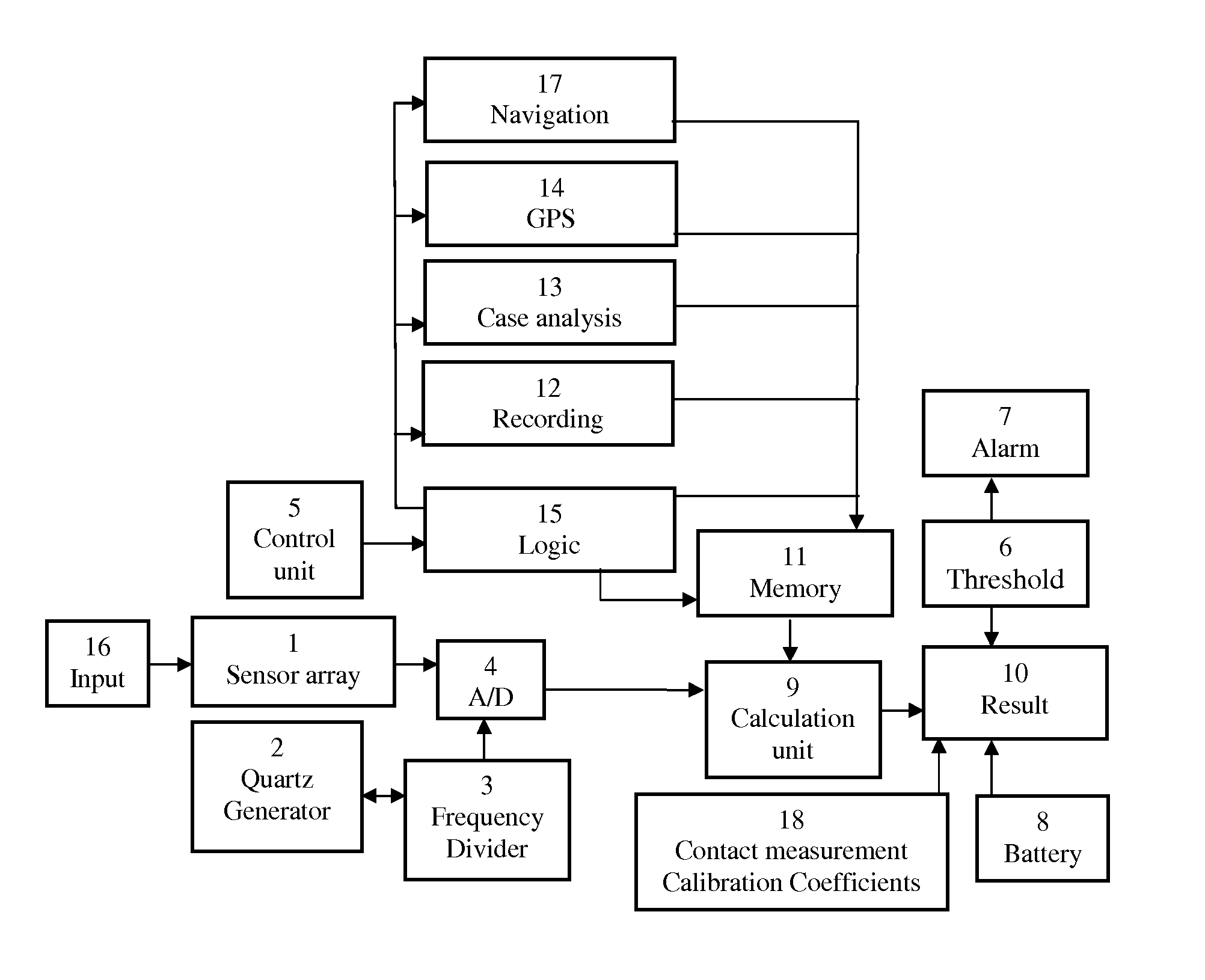
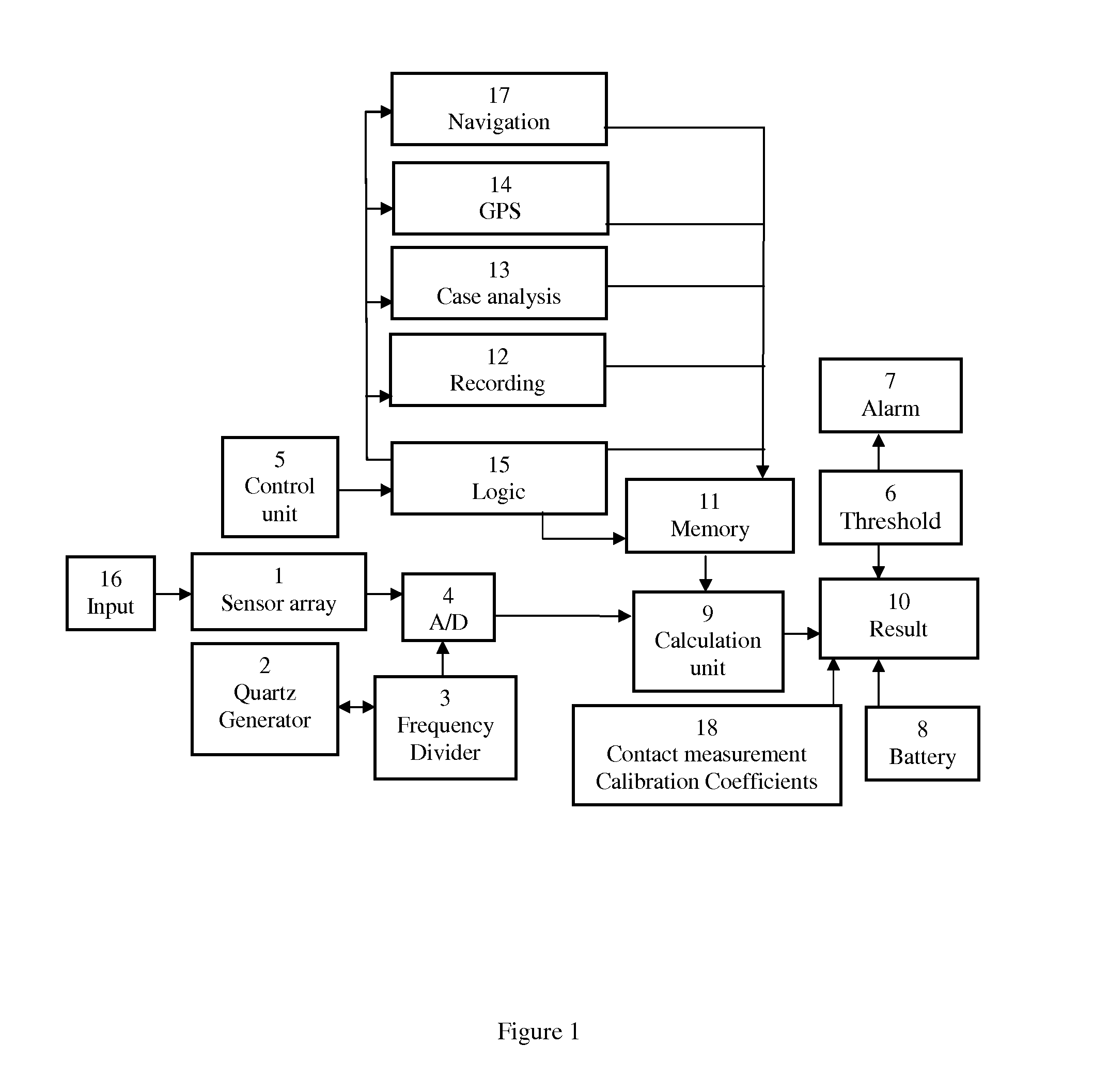
[0050]The present invention describes the magnetic tomography (MT) device for magnetographic identification and analysis of mechanical flaws / defects, optimized for extended metallic constructions inspection. The block-diagram of the method is given in FIG. 1.

[0051]The magnetic tomography device is based on using of the inverse magnetostrictive (Villary) effect—i.e. the changing of the material magnetic susceptibility under applied mechanical stress. Generally, such technique uses “natural” magnetization of the ferrous pipes by magnetic field of the Earth.

[0052]The use of MT device has following advantages: 1) Applicable for the unpiggable pipelines or other objects where in-line inspection method is inapplicable; 2) the objects to be inspected include but not limited to: compressor stations pipelines, pipeline inclusions, water-supply pipelines in cities; 3) the use of MT device doesn't require any preparation of the pipeline for testing such as cleaning, opening the pipe, or stoppi...


PUM


Abstract

A device and method for discovering, identification and monitoring of mechanical flaws in metallic structures is disclosed, based on magneto-graphic / magnetic tomography technique to identify stress-related defects. The technique is specifically optimized for extended, not-accessible underground and underwater metallic structures quality control, emergency alarms as well as timeline planning for structural repairs and maintenance work. Examples of the technique implementation include pipes for oil and gas industry, detection of flaws in rolled products in metallurgical industry, welding quality of heavy duty equipment such as ships, reservoirs, etc. It is especially important for loaded constructions, such as pressured pipes, infrastructure maintenance, nuclear power plant monitoring, bridges, corrosion prevention and environment protection.

Description

CROSS-REFERENCE TO RELATED APPLICATION[0001]This application is a continuation-in-part of the U.S. patent application Ser. No. 13 / 662,427 filed on Oct. 27, 2012.FIELD OF INVENTION[0002]The present invention relates broadly to a device and method for continuous (extended) metallic structures inspection and monitoring for possible mechanical defects; in particular, to magneto-graphic quality control devices and methods, such as magnetic tomography, providing a real-time structural status as well as a priority order for immediate and long-term repairs and maintenance work required.BACKGROUND OF THE INVENTION[0003]This invention can be used in various fields where constructions are tested for continuity defects in not-so-easily accessible areas. Examples of device and method implementation may include pipes for oil and gas industry, detection of flaws in rolled products in metallurgical industry, welding quality of heavy duty equipment such as ships and reservoirs, etc. It is especially...

Claims


Application Information

Patent Timeline
IPC IPC(8): G01V3/00G01R35/00
CPCG01N27/82G01N27/85
Inventor GOROSHEVSKIY, VALERIANKAMAEVA, SVETLANAKOLESNIKOV, IGORIVLEV, LEONID
Owner GOROSHEVSKIY VALERIAN
Why Eureka
Try Eureka