
System and method for isotope selective chemical reactions

a chemical reaction and selective technology, applied in the field of chemical reactions, can solve the problems of not being able to develop an efficient enhancement method and not being properly exploited, and achieve the effect of improving heat exchange and reducing the thickness of the stagnant electrolyte layer

Active Publication Date: 2013-09-17
MATTHEWS MEHLIN DEAN
View PDF15 Cites 2 Cited by
  • Summary
  • Abstract
  • Description
  • Claims
  • Application Information

AI Technical Summary

Benefits of technology

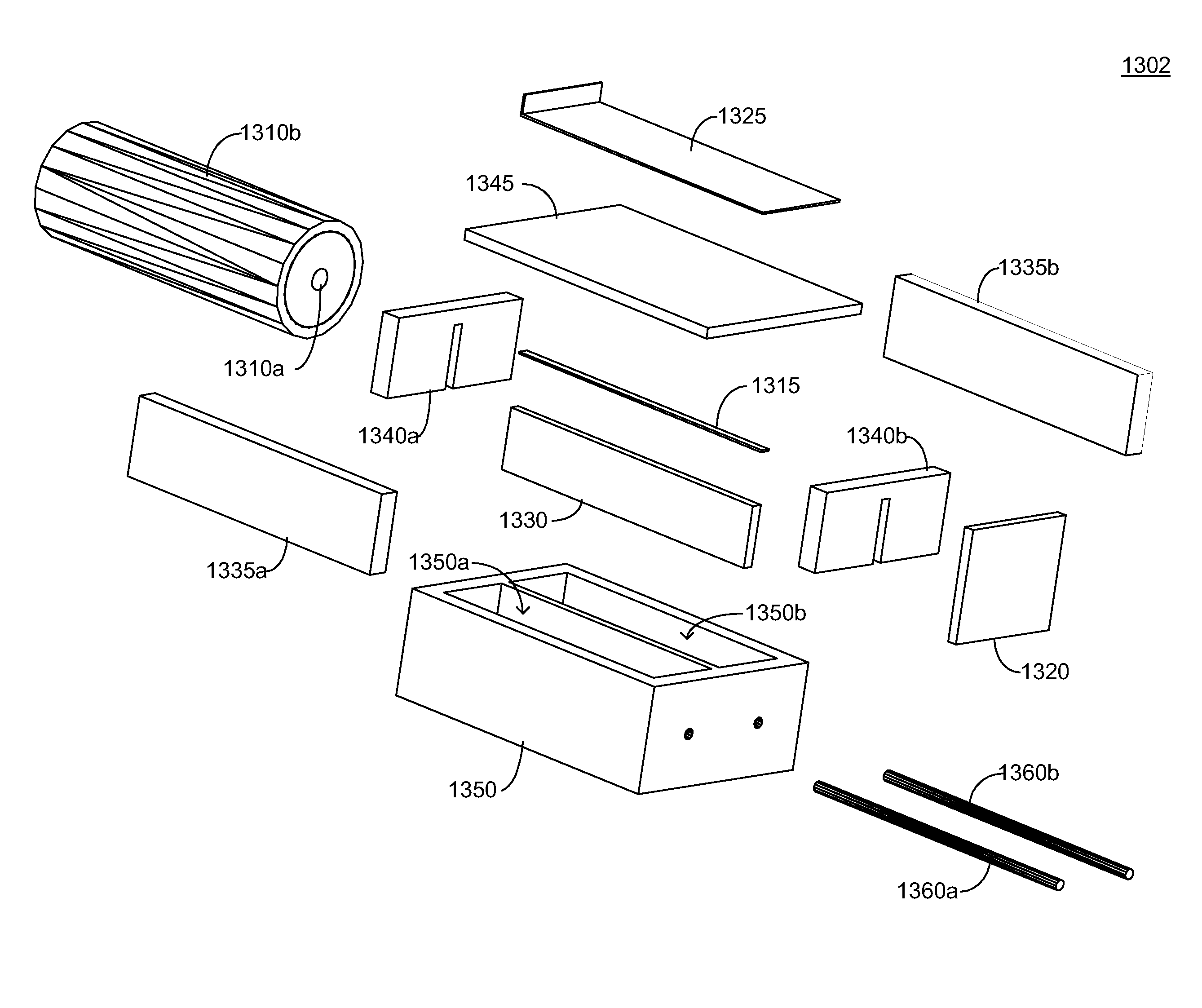
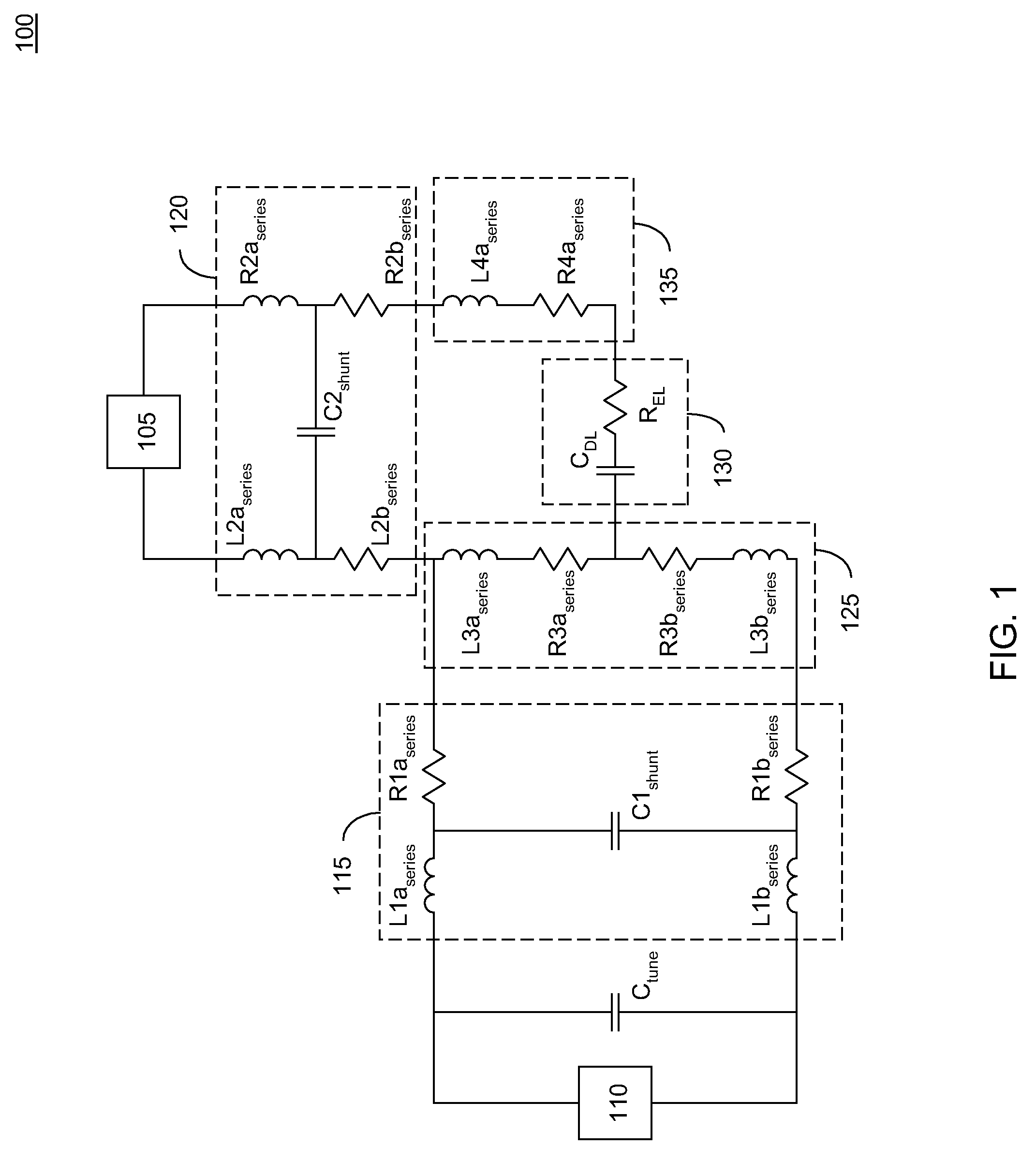
The present invention relates to an electrolytic cell which has a working electrode and a counter electrode. The cell has a high frequency current source coupled to the working electrode to provide an oscillating magnetic field at the surface of the working electrode. An electrolyzing current source is applied across the working electrode and counter electrode of the cell to provide for selective oxidation or reduction at the working electrode. The electrolyte contact area of the working electrode is confined to a portion of a duct wall, so that it is exposed to continuous flow. This results in a thinner stagnant electrolyte layer and improved heat exchange between the working electrode and the electrolyte. The technical effect of this invention is improved electrolytic cell performance and efficiency.

Problems solved by technology

In general, the great variety and complexity of electrochemical systems precludes a comprehensive theoretical model of their behavior, and thus empirical methods must be relied on to a considerable extent.
In 2001, Buchachenko wrote “Besides the many factors controlling nuclear spin selectivity, there are two outstanding and highly promising but not yet properly exploited, microwave induced MIE and dimensionality.” Significantly, although the MIE for uranium and other elements has been established, an efficient approach to enhancement by microwave pumping has not been developed.

Method used


Image

  • System and method for isotope selective chemical reactions
  • System and method for isotope selective chemical reactions
  • System and method for isotope selective chemical reactions

Examples


Embodiment Construction

[0074]The prior art of dynamic spin chemistry has been largely directed to reactions involving radical pairs that occur in bulk solutions, or within micelles or other constrained volumes. The present invention adds a new dimension by addressing the spin modification of ionic species at an electrode surface. Redox reactions at the electrode surface may be used to produce stable products from unstable intermediates that are produced by photolysis and spin modification within the interphase.

[0075]The prior art of spin modification has relied upon microwave radiation to provide the high frequency magnetic field used for pumping unpaired electrons between magnetic energy levels. In contrast, the present invention provides a high frequency magnetic field by providing a current in the redox electrode, or another conductor adjacent to the interphase of the redox electrode. Local magnetic excitation avoids the difficulties associated with radiation propagation and reduces the problems associ...


PUM

PropertyMeasurementUnit
impedanceaaaaaaaaaa
capacitanceaaaaaaaaaa
inductanceaaaaaaaaaa

Abstract

A system providing selective spin modification and reaction in an electrolytic cell. An electrolytic cell is coupled to a magnet that provides a level-splitting magnetic field in a region of electrolyte adjacent to a working electrode, thus establishing a spin resonance for an unpaired electron associated with a chemical species in the region of electrolyte adjacent to the working electrode. The working electrode carries an excitation current produced by a switching source or amplifier. The excitation current produces an alternating magnetic field adjacent to the working electrode that alters the spin state population density for the unpaired electron associated with a chemical species within the electrolyte, thereby enhancing or inhibiting the reaction of the chemical species during subsequent electrolysis.

Description

CROSS-REFERENCE TO RELATED APPLICATIONS[0001]This application is a continuation in part of U.S. application Ser. No. 12 / 109,792, now U.S. Pat. No. 8,043,486, filed Apr. 25, 2008, which in turn is a continuation in part of U.S. application Ser. No. 12 / 036,282, filed Feb. 24, 2008 claiming priority of U.S. application Ser. No. 60 / 990,913, filed Nov. 28, 2007. This application also claims priority of U.S. application Ser. No. 60 / 990,913, filed Nov. 28, 2007. This application is also related to U.S. application Ser. No. 11 / 564,855, now U.S. Pat. No. 7,879,216, filed Nov. 30, 2006, and to U.S. application Ser. No. 11 / 439,932, now U.S. Pat. No. 7,879,206, filed May 23, 2006; which are herein expressly incorporated by reference in their entirety.BACKGROUND OF THE INVENTION[0002]1. Field of the Invention[0003]This invention relates to chemical reactions. In particular, the invention relates to the application of dynamic spin chemistry to electrolytic processes.[0004]2. Description of Relate...

Claims


Application Information

Patent Timeline
Patent Type & Authority Patents(United States)
IPC IPC(8): C25B9/04B03C9/00G01N27/00B03C1/00
CPCC25C1/00C25C1/04C25C1/22C25C7/00H01P3/06C25B9/04C25B9/65
Inventor MATTHEWS, MEHLIN DEAN
Owner MATTHEWS MEHLIN DEAN
Learn More