Analog-digital conversion system comprising a double automatic gain control loop

a conversion system and automatic control technology, applied in the direction of pulse technique, instruments, transmission monitoring, etc., can solve the problems of continuous narrowband interference, limited loss introduced by digitization, interference that continuously affects a portion of the band occupied, etc., and achieve the effect of increasing weigh

Inactive Publication Date: 2013-08-20
THALES SA
View PDF17 Cites 0 Cited by
  • Summary
  • Abstract
  • Description
  • Claims
  • Application Information

AI Technical Summary

Benefits of technology

[0032]According to one advantageous embodiment of the invention, a nonlinearity module is used in the analog AGC loop after comparison, this module having the function of giving more weight to the signal when the latter is not disrupted, that is to say when the estimated power is lower.
[0033]A nonlinearity module is for example used in the digital AGC loop after comparison, this module having the function of giving more weight to the signal when the latter is not disrupted, that is to say when the estimated power is lower.

Problems solved by technology

If the power of the signal at the input of a CAN converter is set to the maximum possible conversion efficiency R, the loss introduced by the digitization is limited.
Continuous narrowband interference is interference that continuously affects a portion of the band occupied by the useful signal.
It can therefore not be eliminated by digital filtering.
In this case, the digital filtering becomes inoperative and a corrupted signal is found at the output.
The drawback of low encoding is that, in the presence of narrowband continuous interference, the quantization noise level rises relative to the useful signal level.
The broadband interference is interference that occupies the whole useful band of the signal.
A band-stop digital filter therefore does not make it possible to sort between the frequencies corrupted by this interference and those that are not.
Moreover, when there is too much pulsed interference, the mean power at the output of the CAN converter increases.
The drawback of this solution is that there is no control of the power at the output of the CAN converter 301.
After saturation, the interference spread throughout the band reappears at the output of the interference-suppressing filter, the loop reacts too late.
Nevertheless, this does not make it possible to control what happens at the input of the CAN converter 301, in particular the risks of saturation.

Method used


Image

  • Analog-digital conversion system comprising a double automatic gain control loop
  • Analog-digital conversion system comprising a double automatic gain control loop
  • Analog-digital conversion system comprising a double automatic gain control loop

Examples


first embodiment

[0051]FIG. 4 shows the analog-digital conversion system according to the invention. The system consists of a transmission chain comprising an analog stage itself consisting of a variable gain amplifier 400. The object of this amplifier is to amplify an analog input signal e. After amplification, the signal is processed by a CAN converter 401 on N bits. The digitized signal at the output of the converter 401 is filtered with the aid of an interference-suppressing digital filter 407. The signal is then used to demodulate the received communication channel(s) 409, 410, 411, 412.

[0052]The analog-digital conversion system according to the invention uses two AGC loops 402, 420 in cascade. The first AGC loop 402 is a conventional analog AGC loop based on an estimate of power at the output of the CAN converter 401. The second AGC loop 420 is called a digital AGC loop based on an estimate of power at the output of the interference-suppressing filter 407 and of which the object is to determin...

second embodiment

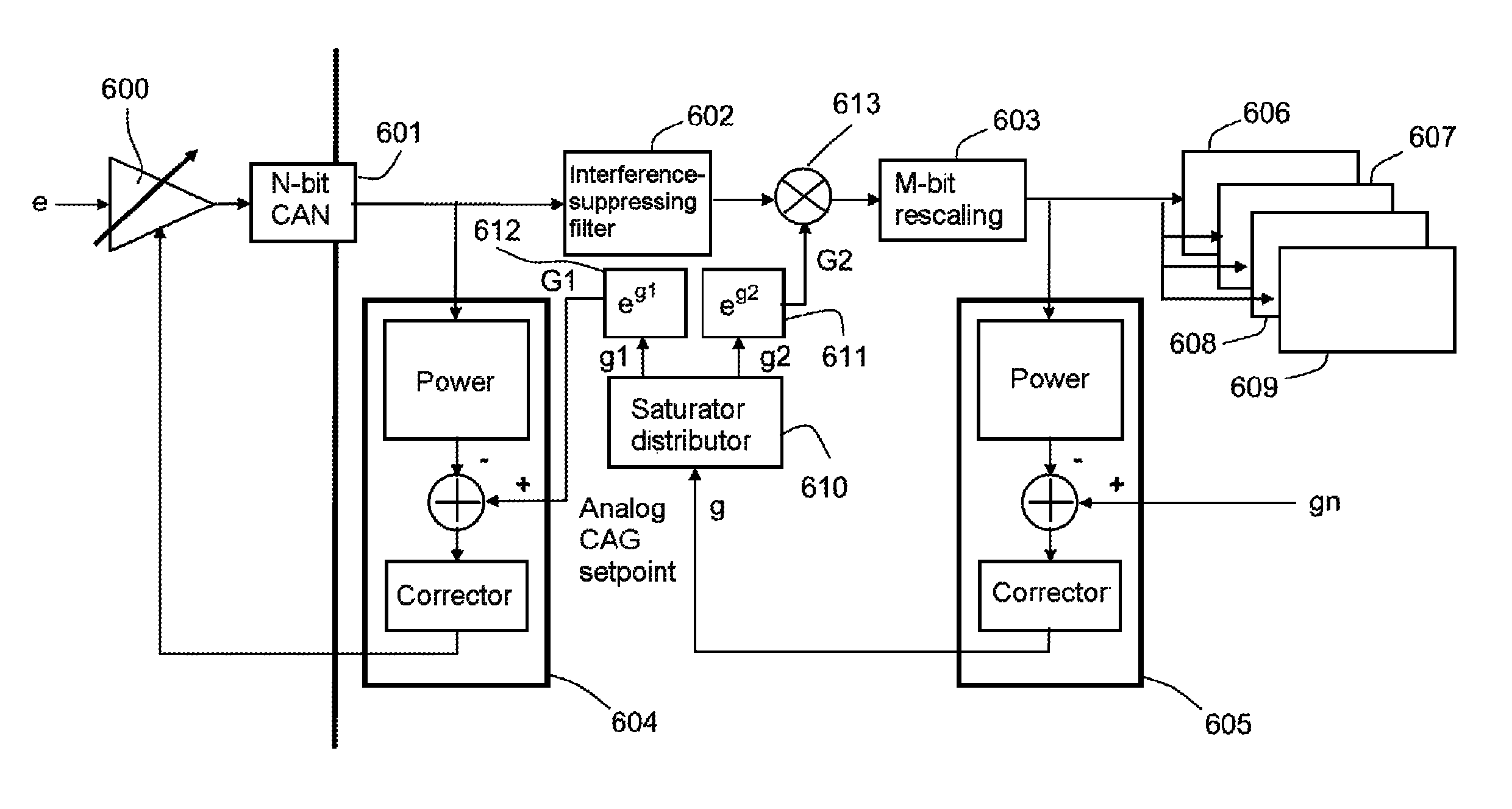
[0064]FIG. 6 shows the analog-digital conversion system according to the invention. The system consists of a transmission chain comprising an analog stage itself consisting of at least one variable gain amplifier 600. The object of this amplifier is to amplify an analog input signal e. After amplification, the signal is processed by a CAN converter 601 on N bits. The digitized signal at the output of the converter 601 is filtered with the aid of an interference-suppressing digital filter 602. The bits at the output of the filter are rescaled on M bits by a rescaling module 603. The digitized and rescaled signal is then used to demodulate 606, 607, 608, 609 the received communication channel(s).

[0065]As for the first embodiment, two AGC loops 604, 605 in cascade are also used. The first AGC loop 604 is a conventional analog AGC loop based on an estimate of the power at the output of the CAN converter 601. The second AGC loop 605 is a digital AGC loop based on an estimate of the power...

third embodiment

[0071]FIG. 8 shows the analog-digital conversion system according to the invention. The system consists of a transmission chain comprising an analog stage itself consisting of a variable gain amplifier 800. The objective of this amplifier is to amplify an analog input signal e. After amplification, the signal is processed by a CAN converter 801 on N bits. The digitized signal at the output of the converter 801 is filtered with the aid of an interference-suppressing digital filter 802. The bits at the output of the filter are rescaled 803 on M bits. The digitized and rescaled signal is then used to demodulate 806, 807, 808, 809 the received communication channel(s).

[0072]As for the first two embodiments, two AGC loops 804, 805 in cascade are used. The first AGC loop 804 is a conventional analog AGC loop based on the output of the CAN converter 801. The second AGC loop 805 is a digital AGC loop based on the output of the interference-suppressing filter 802. A saturation module 810 ded...


PUM


Abstract

An analog-digital conversion system comprising at least one variable gain amplifier amplifying an input signal e, an analog-digital converter CAN digitizing said signal e, an interference-suppressing digital processing module, processing the digitized signal, also comprises a first automatic gain control AGC loop, called the analog AGC loop, that compares an estimate of the output power of the CAN converter with a control setpoint g1 called the control setpoint of the analog AGC loop, a gain ga used to control the variable gain amplifier being deduced from this comparison. The system also comprises a second automatic gain control AGC loop called the digital loop, said digital loop comparing an estimate of the power after the interference-suppressing digital processing with a predetermined control setpoint gn, the analog AGC loop being controlled by a control setpoint deduced from this comparison.

Description

CROSS-REFERENCE TO RELATED APPLICATION[0001]This application claims priority to foreign French patent application No. FR 1101162, filed on Apr. 14, 2011, the disclosure of which is incorporated by reference in its entirety.FIELD OF THE INVENTION[0002]The invention relates to an analog-digital conversion system comprising a double automatic gain control loop and is applied notably to the field of radio communications.BACKGROUND[0003]In a receiver of digital radio communications, the demodulation of the signals is carried out in digital. Before carrying out this demodulation, an analog stage of the receiver brings the signal around an intermediate frequency. The objective of this analog stage is to amplify the signal and to filter it with the aid of an antialiasing filter. After filtering, the signal is digitized using an analog-digital converter usually given the acronym CAN.[0004]In the nominal receiving conditions with no interference, the analog-digital conversion of an analog sig...

Claims


Application Information

Patent Timeline
Patent Type & Authority Patents(United States)
IPC IPC(8): H03M1/12
CPCH03M1/185H03M1/18
Inventor MARTIN, NICOLASPERRE, JEAN-MICHELDEPRAZ, DAVID
Owner THALES SA
Why Eureka
Try Eureka