Electrical harness

a technology of electrical harnesses and harnesses, applied in the direction of insulated conductors, cables, conductors, etc., can solve the problems of high voltage differentials, heavy and difficult to manipulate, bulky conventional harnesses, etc., and achieve the effect of avoiding excessive size, weight and cos

Active Publication Date: 2013-05-09
ROLLS ROYCE PLC
View PDF9 Cites 3 Cited by
  • Summary
  • Abstract
  • Description
  • Claims
  • Application Information

AI Technical Summary

Benefits of technology

The present invention provides an electrical harness that can withstand direct lightning strikes without overvoltages that might damage the circuit board. This is achieved by designing the track layers on the circuit board to have non-overlapping impedance ranges, which reduces the voltage differentials between tracks during a strike. As a result, the harness can maintain its integrity while still meeting its electrical requirements. Additionally, the invention provides a way to use the flexible printed circuit board in gas turbine engines to avoid induced voltage differences between tracks during a strike.

Problems solved by technology

This makes the conventional harness bulky, heavy and difficult to manipulate.
This can result in high voltage differentials between tracks which may produce damage in the harness.
Thus, following IPC standard spacing rules in an FPCB harness which may have to accommodate a potential voltage differential of 1500 V during indirect lightning strikes can lead to the spacing between conductors becoming large, with the result that the harness may become unfeasibly large, heavy and / or expensive.

Method used


Image

  • Electrical harness
  • Electrical harness
  • Electrical harness

Examples


Embodiment Construction

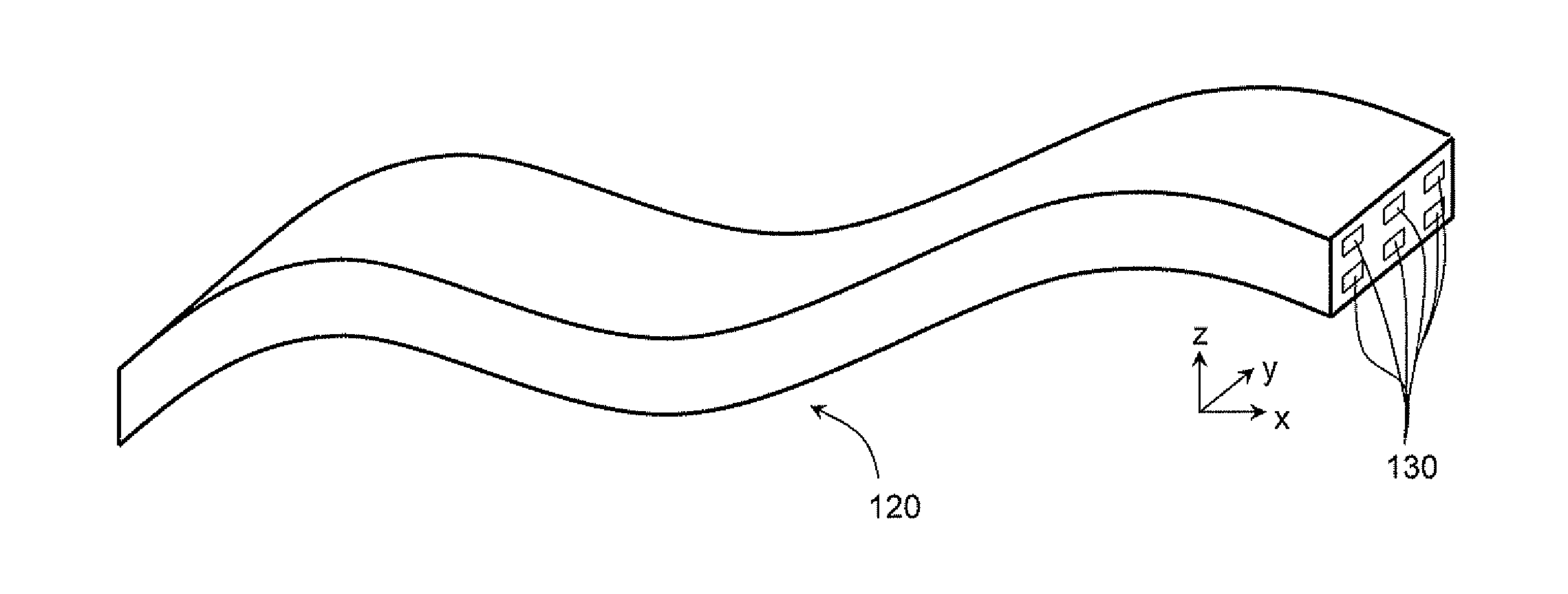
[0046]FIG. 7 shows schematically an arrangement of conductive copper tracks 201a, 201b in a transverse cross-section through an electrical harness formed from a flexible printed circuit board in which the tracks are in two track layers 203. The tracks are not grouped according to the relative impedances of the circuits which they form. Thus, during an indirect lightning strike, high voltage differentials can be induced between adjacent tracks of the same track layer. In particular, tracks 201a forming low impedance circuits, which are typically protected directly or indirectly to ground, remain at or close to ground potential, while tracks 201b forming high impedance circuits, which are typically allowed to “float” above ground, reach potentials of around 1500 V.

[0047]The distance L3 between adjacent tracks of the same track layer thus has to be relatively large to accommodate a potential difference of around 1500 V.

[0048]In contrast, FIG. 8 shows schematically a corresponding arran...


PUM


Abstract

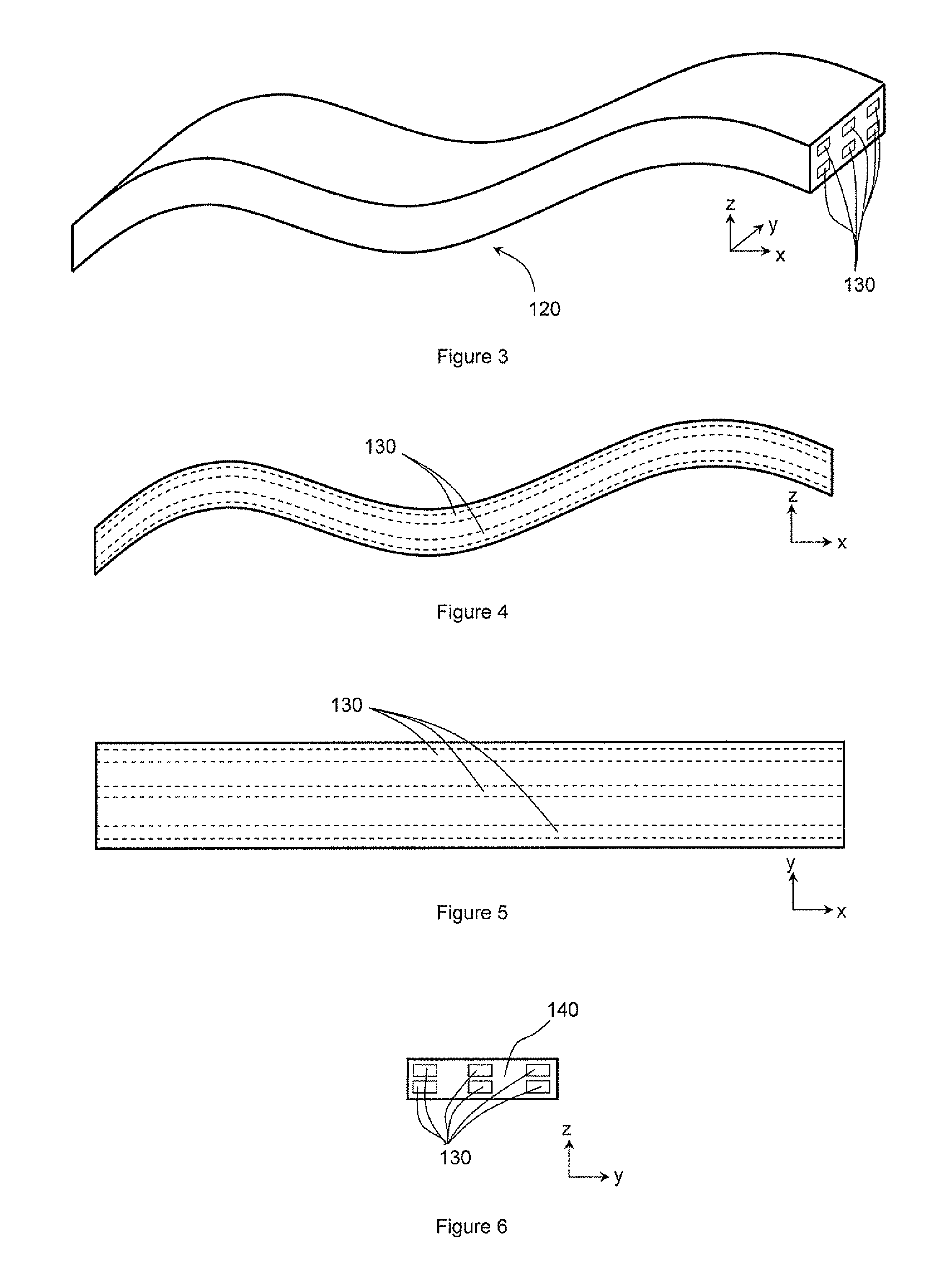
A gas turbine engine has an electrical harness formed from a flexible printed circuit board which provides a plurality of spaced conductive tracks. The conductive tracks are grouped into plural layers of tracks, the track layers being spaced apart and extending substantially parallel to each other. The tracks of each track layer form respective circuits which all have impedances lying within a respective range for that track layer. The impedances ranges are non-overlapping. The highest voltage differentials between tracks produced during indirect lightning strikes will thus tend to be between tracks of different track layers rather than between tracks of the same track layer.

Description

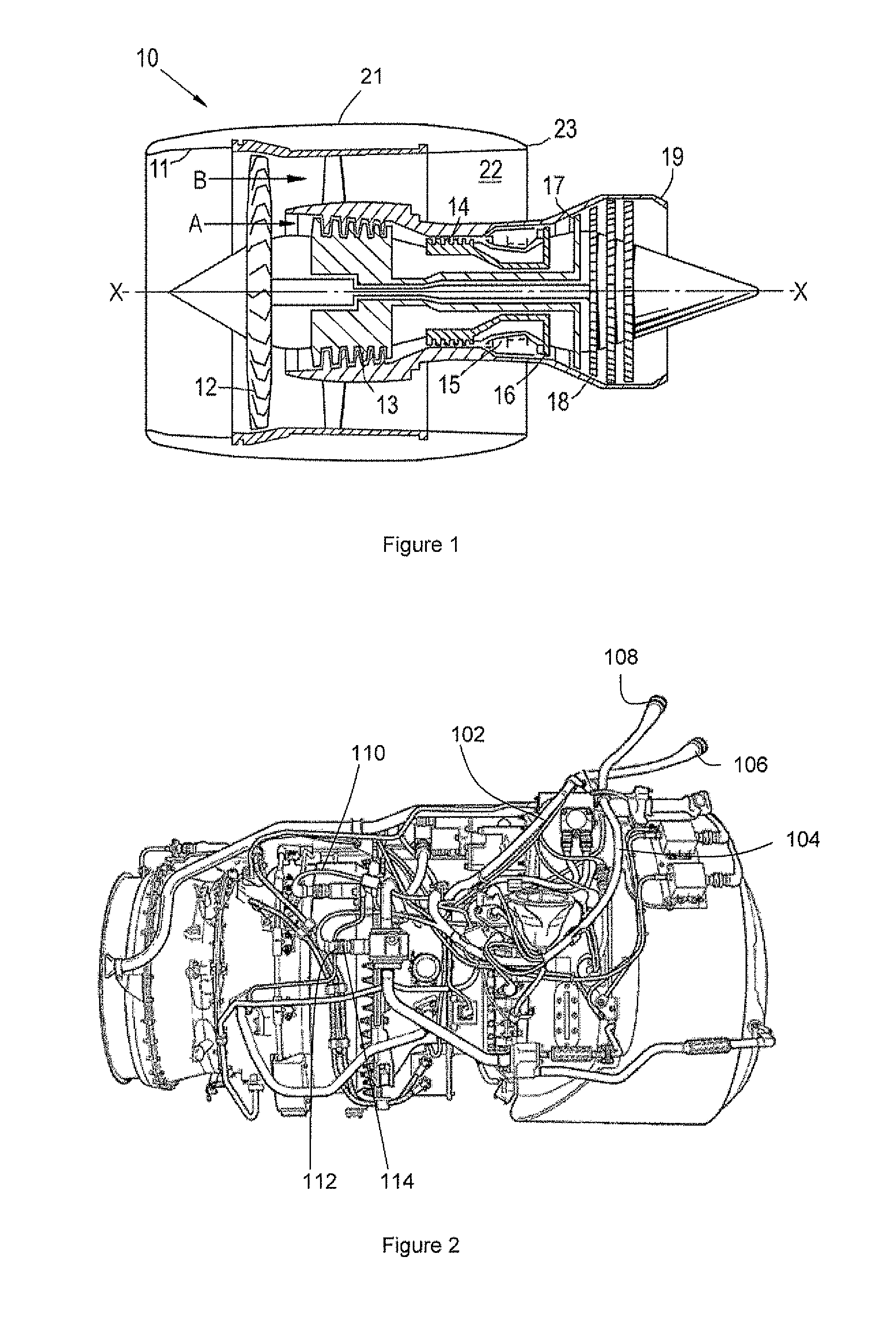
CROSS-REFERENCE TO RELATED APPLICATIONS[0001]This application is based upon and claims the benefit of priority from British Patent Application Number 1119046.9 filed 4 Nov. 2011, the entire contents of which are incorporated by reference.[0002]1. Field of the Invention[0003]The present invention relates to an electrical harness formed from a flexible printed circuit board.[0004]2. Background of the Invention[0005]With reference to FIG. 1, a ducted fan gas turbine engine generally indicated at 10 has a principal and rotational axis X-X. The engine comprises, in axial flow series, an air intake 11, a propulsive fan 12, an intermediate pressure compressor 13, a high-pressure compressor 14, combustion equipment 15, a high-pressure turbine 16, and intermediate pressure turbine 17, a low-pressure turbine 18 and a core engine exhaust nozzle 19. A nacelle 21 generally surrounds the engine 10 and defines the intake 11, a bypass duct 22 and a bypass exhaust nozzle 23.[0006]The gas turbine eng...

Claims


Application Information

Patent Timeline
Patent Type & Authority Applications(United States)
IPC IPC(8): H02G3/04
CPCH05K1/02F02C7/32H05K1/0298H05K1/0393Y02T50/60B60R16/0207H05K1/0257H05K1/0277H05K1/189F02C7/00
Inventor WATKISS, JASON
Owner ROLLS ROYCE PLC
Why Eureka
Try Eureka