Film scanner

a scanner and film technology, applied in the field of film scanners, can solve the problems of unwanted wear of the perforation holes, reduced mechanical registration speed, and reduced accuracy, and achieve the effect of high precision

Active Publication Date: 2013-07-30
ARNOLD & RICHTER CINE TECHN & BETRIEBS
View PDF29 Cites 0 Cited by
  • Summary
  • Abstract
  • Description
  • Claims
  • Application Information

AI Technical Summary

Benefits of technology

[0009]It is the object of the invention to avoid an image shift in a film scanner on the...

Problems solved by technology

A mechanical registration of this type, however, results in unwanted wear of the perforation holes.
Aged footage 5 can have shrunk or be very brittle so that it can be damaged on the introduction of the registration pins into the perforation holes.
A further disadvantage in film scanners having intermittent ...

Method used


Image

  • Film scanner
  • Film scanner
  • Film scanner

Examples


Embodiment Construction

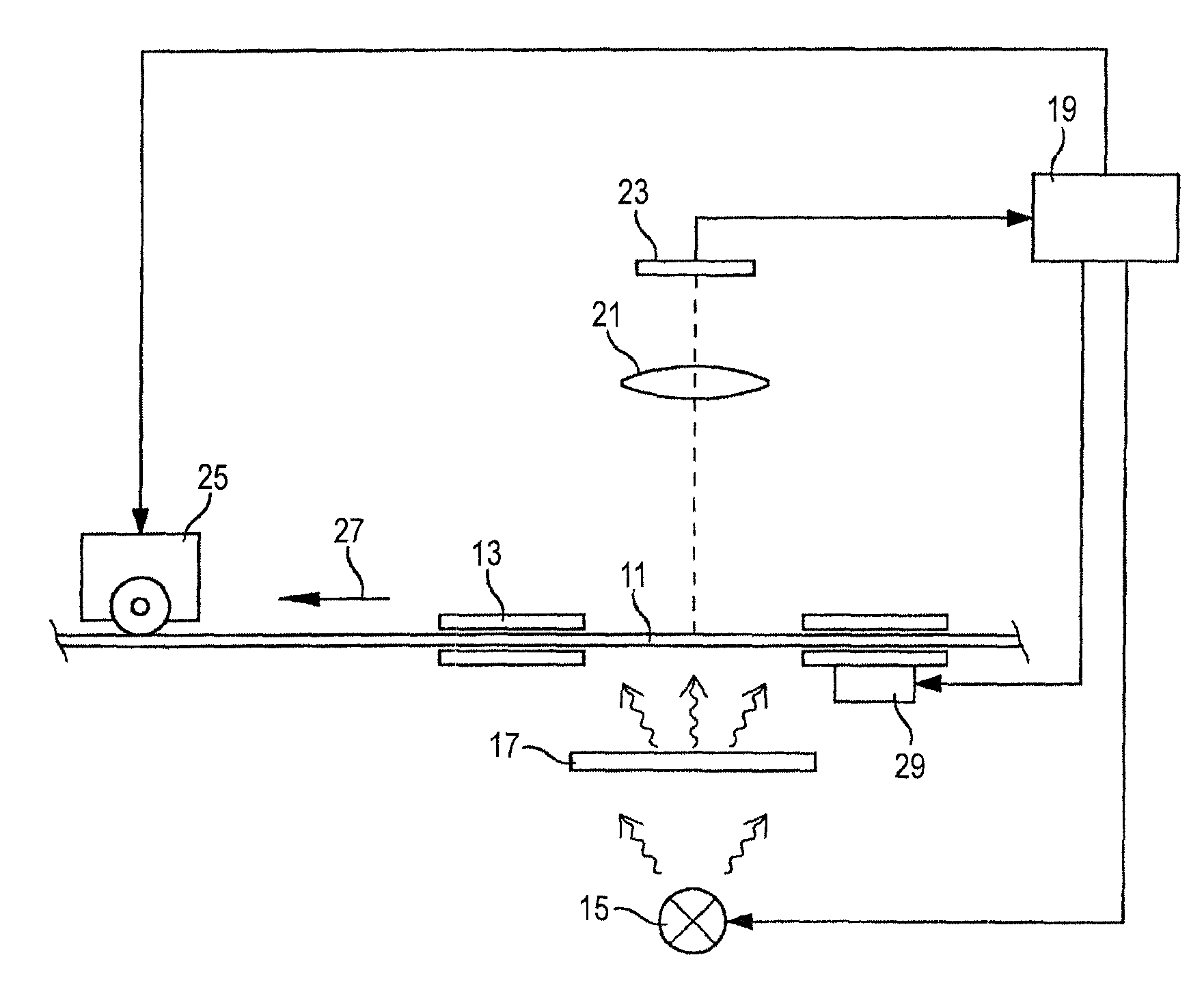
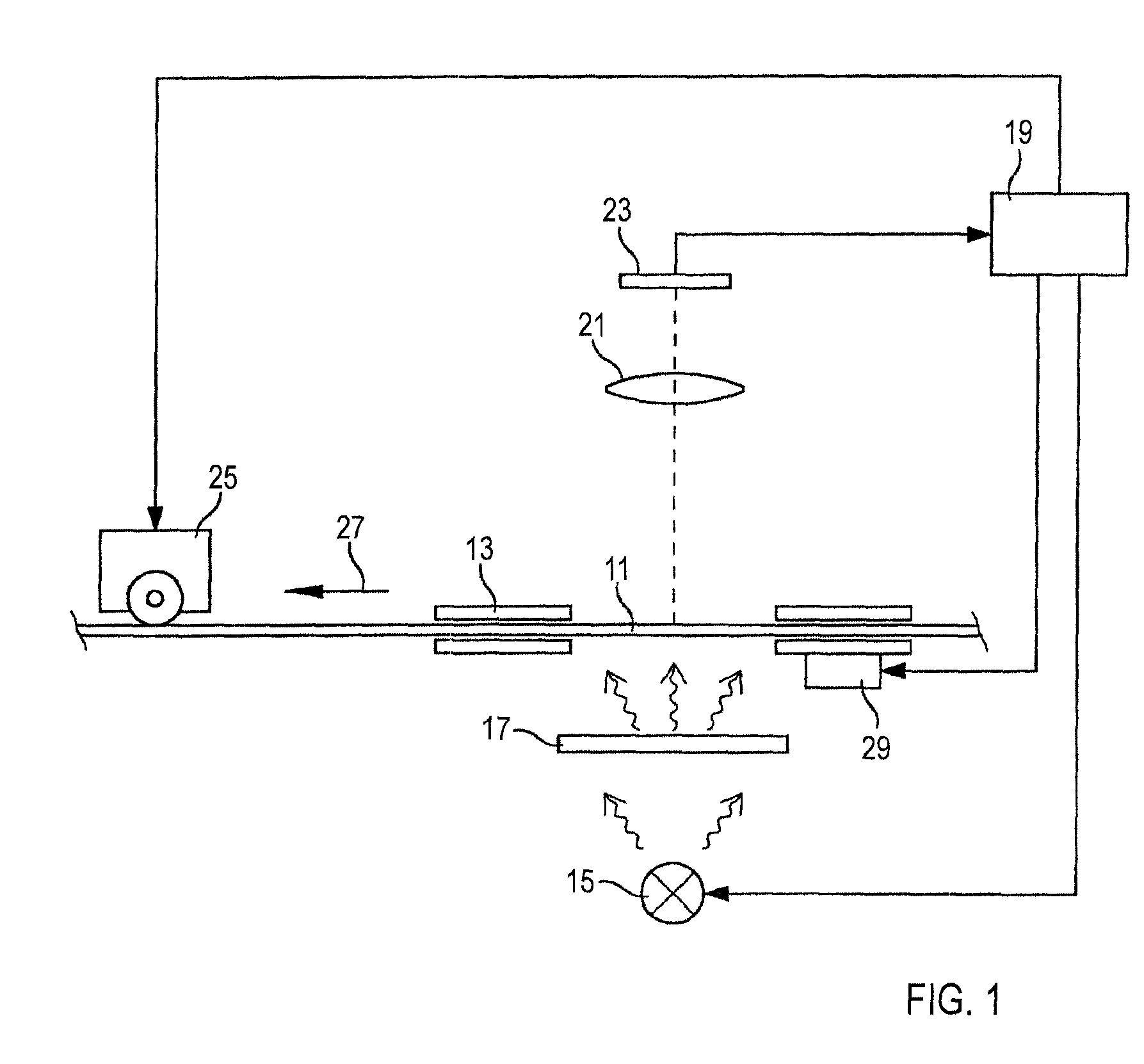
[0034]FIG. 1 illustrates the design of a film scanner for the optical scanning of an 30 exposed motion picture film 11, which is guided in a film track 13. The motion picture film 11 or a respective exposed image region thereof is illuminated by means of a light source 15 and a downstream diffuser 17. An optical receiving system 21, which is shown by way of example as a converging lens, is arranged on the side of the motion picture film 11 disposed opposite the light source 15. The optical receiving system 21 images the image region of the motion picture film 11 to be scanned onto an optoelectronic image sensor 23 which is made, for example, as a CCD or CMOS sensor having a matrix-type arrangement of photoelectric reception elements. The reception elements generate a respective picture element measured value in dependence on the light exposure, with the image sensor 23 being connected to an input of a control and evaluation unit 19.

[0035]The optical scanning of the motion picture fi...


PUM


Abstract

A film scanner for the optical scanning of a motion picture film having a sequence of a plurality of image regions and at least one row of a plurality of perforation holes in the longitudinal direction, in particular a motion picture film of the type 16 mm or 35 mm, comprises an image sensor for the detection at least of a respective image region of the motion picture film to generate a corresponding scanned image. The film scanner further comprises an evaluation unit for the evaluation of the scanned image to generate an image steadiness correction signal. The image sensor is made for the additional detection of only a respective part region of perforation holes in the environment of the detected image region of the motion picture film, with the evaluation unit being made to determine a position of the detected part region of at least one perforation hole. The evaluation unit generates the image steadiness correction signal on the basis of the at least one determined part region position.

Description

BACKGROUND OF INVENTION[0001]1. Field of Invention[0002]The invention relates to a film scanner and to a method for the optical scanning of a motion picture film.[0003]2. Description of Prior Art[0004]A film scanner of this type serves for the scanning of the image information of an exposed film, for example for the purpose of digital post-processing. A transmission arrangement is usually provided for this purpose, with the film material to be scanned being illuminated on the one side and an optical receiving system and a light receiver being arranged on the other side.[0005]The motion picture film is transmitted intermittingly in such a film scanner to sequentially illuminate the individual exposed image sections, i.e. the individual image sections following one another, and to scan them optically. It is desired in this process to scan a sequence of mutually following individual image sections without any image shift, in particular without any horizontal image shift (weave) and wit...

Claims


Application Information

Patent Timeline
IPC IPC(8): H04N3/02H04N9/10H04N5/77
CPCH04N3/36H04N5/253
Inventor CIESLINSKI, MICHAEL
Owner ARNOLD & RICHTER CINE TECHN & BETRIEBS
Why Eureka
Try Eureka