
Friction weld coaxial connector and interconnection method

a technology of friction welding and coaxial connector, which is applied in the direction of auxillary welding devices, cable terminations, insulation conductors/cables, etc., can solve the problems of complex manufacture and installation, and the interconnection may be less than satisfactory

Inactive Publication Date: 2013-07-09
COMMSCOPE TECH LLC
View PDF31 Cites 24 Cited by
  • Summary
  • Abstract
  • Description
  • Claims
  • Application Information

AI Technical Summary

Benefits of technology

[0031]Aluminum has been applied as a cost-effective alternative to copper for the conductors in coaxial cables. However, aluminum oxide surface coatings quickly form upon air-exposed aluminum surfaces. These aluminum oxide surface coatings may degrade traditional mechanical, solder and / or conductive adhesive interconnections.
[0056]One skilled in the art will appreciate that the connector and interconnection method disclosed has significant material cost efficiencies and provides a permanently sealed interconnection with reduced size and / or weight requirements.

Problems solved by technology

Although this type of connector is typically removable / re-useable, manufacturing and installation is complicated by the multiple separate internal elements required, interconnecting threads and related environmental seals.
However, solder and / or adhesive interconnections may be difficult to apply with high levels of quality control, resulting in interconnections that may be less than satisfactory, for example when exposed to vibration and / or corrosion over time.

Method used


Image

  • Friction weld coaxial connector and interconnection method
  • Friction weld coaxial connector and interconnection method
  • Friction weld coaxial connector and interconnection method

Examples


Embodiment Construction

[0031]Aluminum has been applied as a cost-effective alternative to copper for the conductors in coaxial cables. However, aluminum oxide surface coatings quickly form upon air-exposed aluminum surfaces. These aluminum oxide surface coatings may degrade traditional mechanical, solder and / or conductive adhesive interconnections.

[0032]The inventors have recognized that increasing acceptance of coaxial cable with solid outer conductors of aluminum and / or aluminum alloy enables connectors configured for interconnection via friction welding between the outer conductor and a connector body which may also be cost effectively provided, for example, formed from aluminum and / or aluminum alloy.

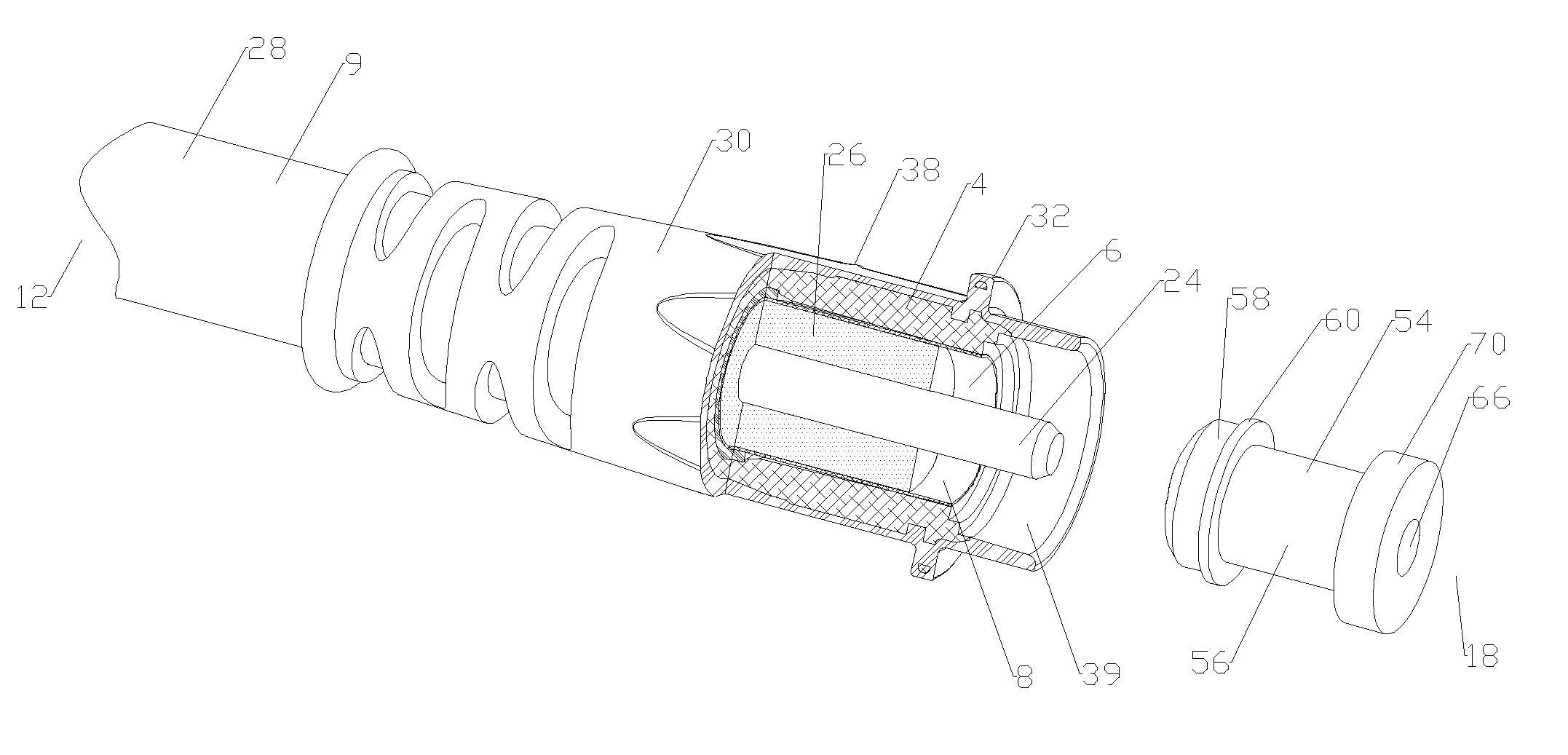
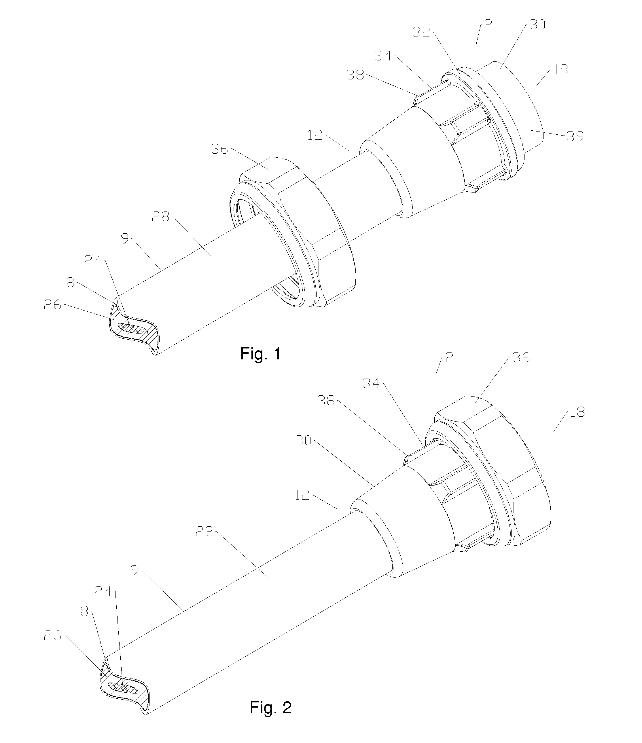
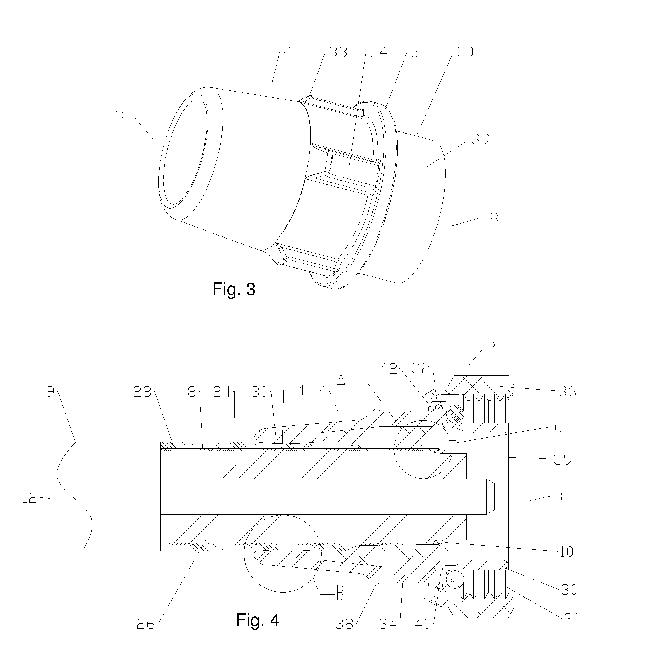
[0033]An exemplary embodiment of a friction weldable coaxial connector 2 is demonstrated in FIGS. 1-4. As best shown in FIG. 4, a unitary connector body 4 is provided with a bore 6 dimensioned to receive the outer conductor 8 of a coaxial cable 9 therein. An inward projecting shoulder 10 angled toward a ca...


PUM

PropertyMeasurementUnit
outer diameteraaaaaaaaaa
inner diameteraaaaaaaaaa
frictionaaaaaaaaaa

Abstract

A coaxial connector for interconnection with a coaxial cable with a solid outer conductor by friction welding is provided with a monolithic connector body with a bore dimensioned for an interference fit with an outer diameter of the outer conductor. A friction groove may be formed around the leading end of the outer conductor by application of a friction weld support against the inner diameter and leading end of the outer conductor. The friction groove may include a material chamber formed between a radial friction protrusion of the bore and a bottom of the friction groove. The friction weld support may be provided with ceramic surfaces contacting the outer conductor, a stop shoulder dimensioned to abut a cable end of the bore and / or an elastic insert seated within an inner conductor bore.

Description

BACKGROUND[0001]1. Field of the Invention[0002]This invention relates to electrical cable connectors. More particularly, the invention relates to a coaxial cable connector interconnectable via friction welding.[0003]2. Description of Related Art[0004]Coaxial cable connectors are used, for example, in communication systems requiring a high level of precision and reliability.[0005]To create a secure mechanical and optimized electrical interconnection between the cable and the connector, it is desirable to have generally uniform, circumferential contact between a leading edge of the coaxial cable outer conductor and the connector body. A flared end of the outer conductor may be clamped against an annular wedge surface of the connector body via a coupling body. Representative of this technology is commonly owned U.S. Pat. No. 6,793,529 issued Sep. 21, 2004 to Buenz. Although this type of connector is typically removable / re-useable, manufacturing and installation is complicated by the mu...

Claims


Application Information

Patent Timeline
Patent Type & Authority Patents(United States)
IPC IPC(8): H01B13/20
CPCB23K20/129H01R43/20H01R9/05H01R43/0207H01R4/029B23K2201/38Y10T29/49204Y10T29/49Y10T29/49179Y10T29/49117Y10T29/49929Y10T29/49123Y10T29/49002B23K2101/38
Inventor VAN SWEARINGEN, KENDRICKVACCARO, RONALD ALANFLEMING, JAMES P
Owner COMMSCOPE TECH LLC
Learn More