
Controlling operation of a processor according to execution mode of an instruction sequence

a technology of instruction sequence and execution mode, applied in the direction of instruments, digital computers, computation using denominational number representation, etc., can solve the problems of asynchronous event induced failure, inability to rely on even short sequences of instructions taking a predictable time, and difficulty in achieving user-control over the precise semantics of instruction execution

Active Publication Date: 2013-06-25
SUN MICROSYSTEMS INC
View PDF10 Cites 52 Cited by
  • Summary
  • Abstract
  • Description
  • Claims
  • Application Information

AI Technical Summary

Benefits of technology

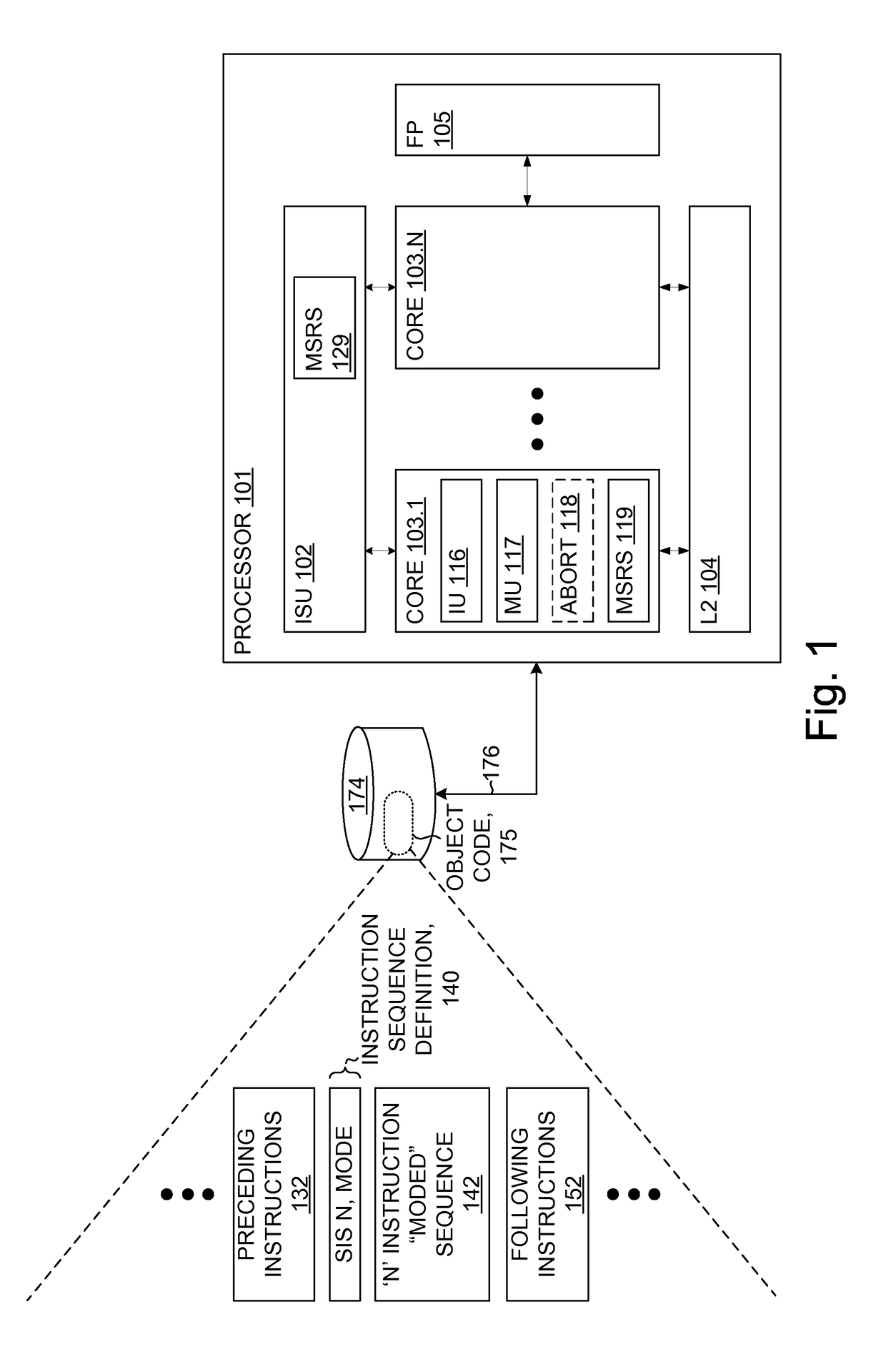
The invention provides a method for controlling the operation of a processor according to the manner in which an instruction sequence is executed. This helps to improve the efficiency and accuracy of processing. The invention includes an instruction supply unit, a control circuit, and execution units. The instruction supply unit supplies information derived from instructions in an instruction stream to the execution units. The control circuit recognizes the start of an instruction sequence and controls the operation of the instructions based on the execution mode specified in the instruction sequence definition. The invention enables efficient processing and improved performance.

Problems solved by technology

One issue in some processor systems is difficulty of achieving user-control over the precise semantics of instruction execution.
First, programs wishing to do accurate timing or tracing are not able to rely on even short sequences of instructions taking a predictable time due to asynchronous events that temporarily disrupt normal program flow.
Second, in some usage scenarios and with some code sequences, such as those doing state-switching, an asynchronous event induces a failure.

Method used


Image

  • Controlling operation of a processor according to execution mode of an instruction sequence
  • Controlling operation of a processor according to execution mode of an instruction sequence
  • Controlling operation of a processor according to execution mode of an instruction sequence

Examples


example embodiments

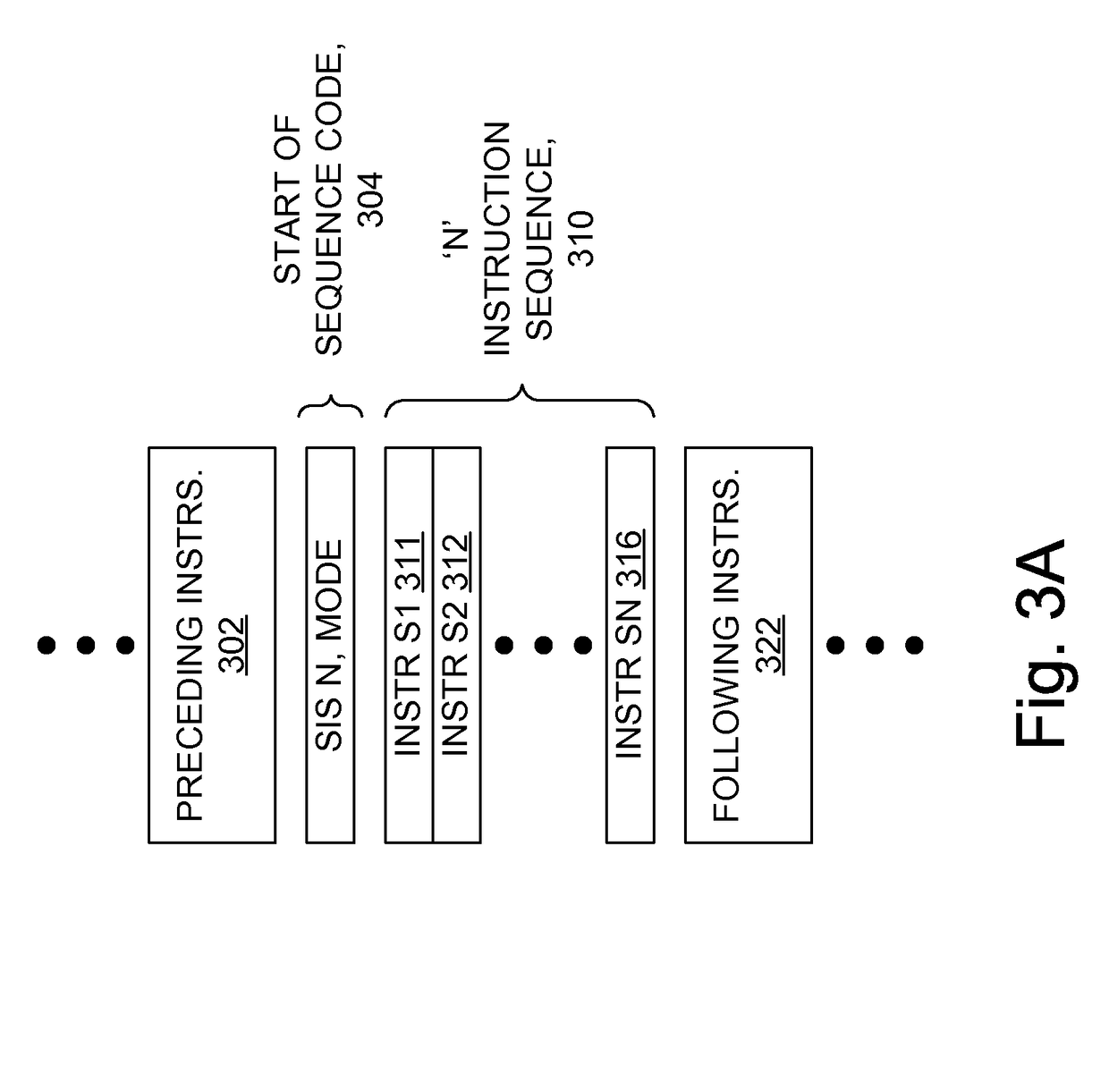
[0137]In some embodiments, such as a first example embodiment, a method for executing instruction sequences in a processor includes: executing instructions of an instruction stream according to a first execution mode; recognizing in the instruction stream a start of sequence code, the start of sequence code associated with an instruction sequence definition specifying an instruction sequence in the instruction stream, the instruction sequence including one or more instructions; subsequent to the recognizing, executing the instruction sequence according to a second execution mode; and subsequent to the instruction sequence execution, continuing execution of the instruction stream according to a third execution mode.

[0138]In some embodiments, such as a second example embodiment, a method for executing instruction sequences in a processor includes: executing instructions of an instruction stream according to a first execution mode; providing an instruction sequence definition specifyin...


PUM


Abstract

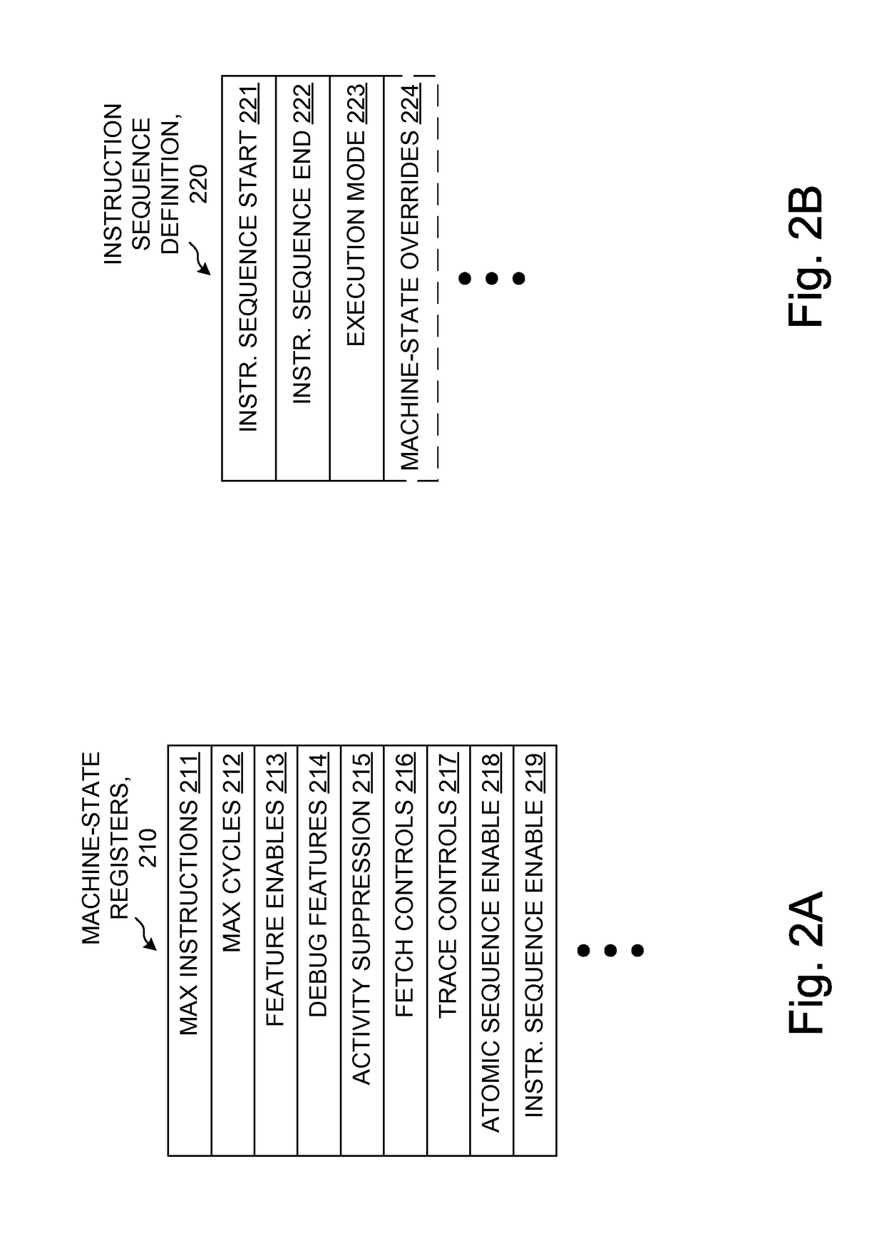
In a processor, instructions of an instruction stream are supplied to an execution unit which executes the supplied instructions according to respective execution modes. A control unit recognizes a user-defined instruction sequence (UDIS) in the instruction stream. The UDIS is associated with a UDIS definition provided in-line and / or as contents of machine-state registers (MSRs), and specifying, at least in part, a start, optionally an end, and a particular execution mode for the UDIS. Subsequently, ones of the instructions of the UDIS are executed in accordance with the particular execution mode, such as by optionally altering recognition of asynchronous events. For example, disabling hardware interrupts during the executing results in apparent atomic execution. Fetching, decoding, issuing, and / or caching of the instructions of the UDIS are optionally dependent on the particular execution mode. MSRs optionally specify a maximum length and / or execution time.

Description

CROSS REFERENCE TO RELATED APPLICATIONS[0001]Priority benefit claims for this application are made in the accompanying Application Data Sheet (if any). To the extent permitted by the type of the instant application, this application incorporates by reference for all purposes the following application(s), which are all owned by the owner of the instant application:[0002]U.S. Provisional Application Ser. No. 60 / 721,385, filed Sep. 28, 2005, first named inventor Leonard Shar, and entitled EFFICIENT TRACE CACHE MANAGEMENT DURING SELF-MODIFYING CODE PROCESSING;[0003]U.S. Provisional Application Ser. No. 60 / 730,550, filed Oct. 26, 2005, first named inventor John Gregory Favor, and entitled CHECKPOINTING STATUS FLAGS FOR ATOMIC TRACES;[0004]U.S. Provisional Application Ser. No. 60 / 730,810, filed Oct. 27, 2005, first named inventor Greg Favor, and entitled ALLOCATION AND DEALLOCATION OF SHADOW REGISTERS USED BY ATOMIC TRACES;[0005]U.S. Provisional Application Ser. No. 60 / 731,962, filed Oct....

Claims


Application Information

Patent Timeline
Patent Type & Authority Patents(United States)
IPC IPC(8): G06F9/00
CPCG06F9/00G06F9/30076G06F9/30101G06F9/30189G06F9/3808G06F9/382G06F9/3836G06F9/3858
Inventor KENVILLE, THOMAS JAMESNADKARNI, ANSHUMAN SHRIKANT
Owner SUN MICROSYSTEMS INC
Learn More