
System and method for using three dimensional infrared imaging to provide detailed anatomical structure maps

a technology of infrared anatomical imaging and detailed anatomical structure, applied in the field of infrared imaging, can solve the problems of prone to errors in manually segmenting a structure in three-dimensional data, requiring a longer scanning time, and requiring expensive scanning time, so as to reduce the limitations of each sensor

Inactive Publication Date: 2013-06-11
PROKOSKI FRANCINE J
View PDF3 Cites 103 Cited by
  • Summary
  • Abstract
  • Description
  • Claims
  • Application Information

AI Technical Summary

Benefits of technology

This approach enables accurate and automated standardization and comparison of medical images, improving diagnostic efficiency and security by providing a scalable and secure biometric identification system resistant to forgery.

Problems solved by technology

However it is expensive and generally requires a longer scanning time than CT.
All produce images oriented to body-centric models, but fusion of images from multiple sensor modalities is neither automatic nor precise.
Segmentation in IR images shares technical issues with MRI images.
Manually segmenting a structure in three-dimensional data is prone to errors.
This slice-by-slice approach to manual segmentation is time consuming and generally suffers from poor reproducibility of results for a given analyst, as well as variations among analysts.
The image data acquired is noisy and often difficult to interpret.
The main drawbacks of maximum intensity projections are the overlap of non-vascular structures and the fact that small vessels with low contrast are barely visible.
This has been a main limitation in time-of-flight MRA.
All these methods have shown problems to detect vessels over a large size range since they perform a fixed scale analysis.
If no motion artifacts are present, the subtracted images are of such good quality, that further processing is not desirable.
Patient anomalies such as a lesion can distort the results.
Non-linear normalization routines may try to minimize the anomaly by compressing that region—distorting the area of the image in the process and causing imprecision in location and size of the lesion in the normalized image.
Using only linear normalization results in less risk of significant local distortion, providing better overall coregistration, although not achieving optimal local registrations.
Furthermore, nonlinear functions are more heavily influenced by local image information, and therefore nonlinear normalization of patient scans may lead to distortion due to the unusual appearance of the anomaly.
However, even when used in a verification mode (one-to-one matching) resulting error rates are too high to justify unattended access control into secure areas.
When used to screen for persons on a Watch List (one-to-many matching) the resulting false alarm rates create unacceptable delays if the Watch List contains more than a few dozen people.
Integrating multiple biometrics (in particular combining face recognition and fingerprint matching) and upgrading visual face recognition to 3D can improve system accuracy, but may degrade system speed and reliability to unacceptable levels.
Current biometric technologies are not secure against sophisticated adversaries intent on forging another person's biometric identity.
Any biometric system relying on features that can be covertly collected and forged cannot guarantee security against future forgery methods.
Biometric identification based on the use of subsurface anatomical features provides security against biometric identity theft because the features are not readily observable to would-be forgers.
Even if the sensor or the anatomical information from an authorized person is easy to obtain, it should be impossible for one person to surgically alter his anatomical features to mimic those of another person without leaving evidence that he has done so.
Facial surgery that was sufficiently extensive to fool a 3D / IR system would necessarily pose a significant risk of death.
The transition to automated livescan sensors in theory offers the same or better potential image quality; however, the self-imaging procedure does not provide consistent quality images and the users may not be trained or motivated to assure maximum quality.
Current biometric systems give unacceptable performance when large populations are enrolled; even when lighting conditions are ideal and even when there is no attempt at sophisticated disguises or forged identities.
Visual face recognition techniques require controlled lighting, are vulnerable to normal daily changes in appearance as well as to intentional disguise, and do not have sufficient feature complexity or density for scalability to a billion people.
Other biometrics such as iris scanning or fingerprints require close or contact distances and cannot be performed in realtime with non-cooperating subjects.
Two-dimensional visual face recognition cannot provide the required performance when lighting varies, an extended period of time intervenes, or there is a change in appearance caused by aging, illness, cosmetics, disguise, or surgery.
Variations in landmark selection points create significant differences in scaling and can be seriously affected by intentional disguises, facial expressions, makeup, sunburns, shadows and similar unintentional disguises.
However, thermal contour analysis of IR facial images is not sufficiently accurate or fast when used against very large databases or when imagery to be compared has different positions of the subject's head, or different temperature distributions, since those produce significant changes to the thermal contours used for identification.
That is, the approach is computationally intensive, requires a pre-formed database, and requires standardization of the images through pre-processing.
Current biometric techniques including: hand geometry, fingerprints, retina and iris scanning, voice recognition, and visual facial recognition each has inherent technical limitations that prevent satisfying all those requirements.
Both eyewitness and automated face recognition suffer from vulnerability to lighting changes.
Different people in the same environment may have average face temperatures differing by six degrees or more; and an individual's face may display a 10 degree variation in temperature, producing saturated areas in the imagery, with resulting loss of data, if the camera has insufficient bandwidth.
All current biometrics have serious inherent limitations in non-cooperative identification against very large databases.
In particular, iris and retinal scanning, hand and fingerprints require active cooperation by the subject at close distance and are therefore relatively slow, require training, and cannot be used for covert or non-cooperative identification.
Face recognition based on visual images can be performed from long distances without cooperation, but is prone to changes in illumination, intentional disguises, and similarity in appearance of many people.
Therefore, there has been no scientific basis for claiming that two partial fingerprints are from the same person if they contain a specific number of similar minutiae characteristics.

Method used


Image

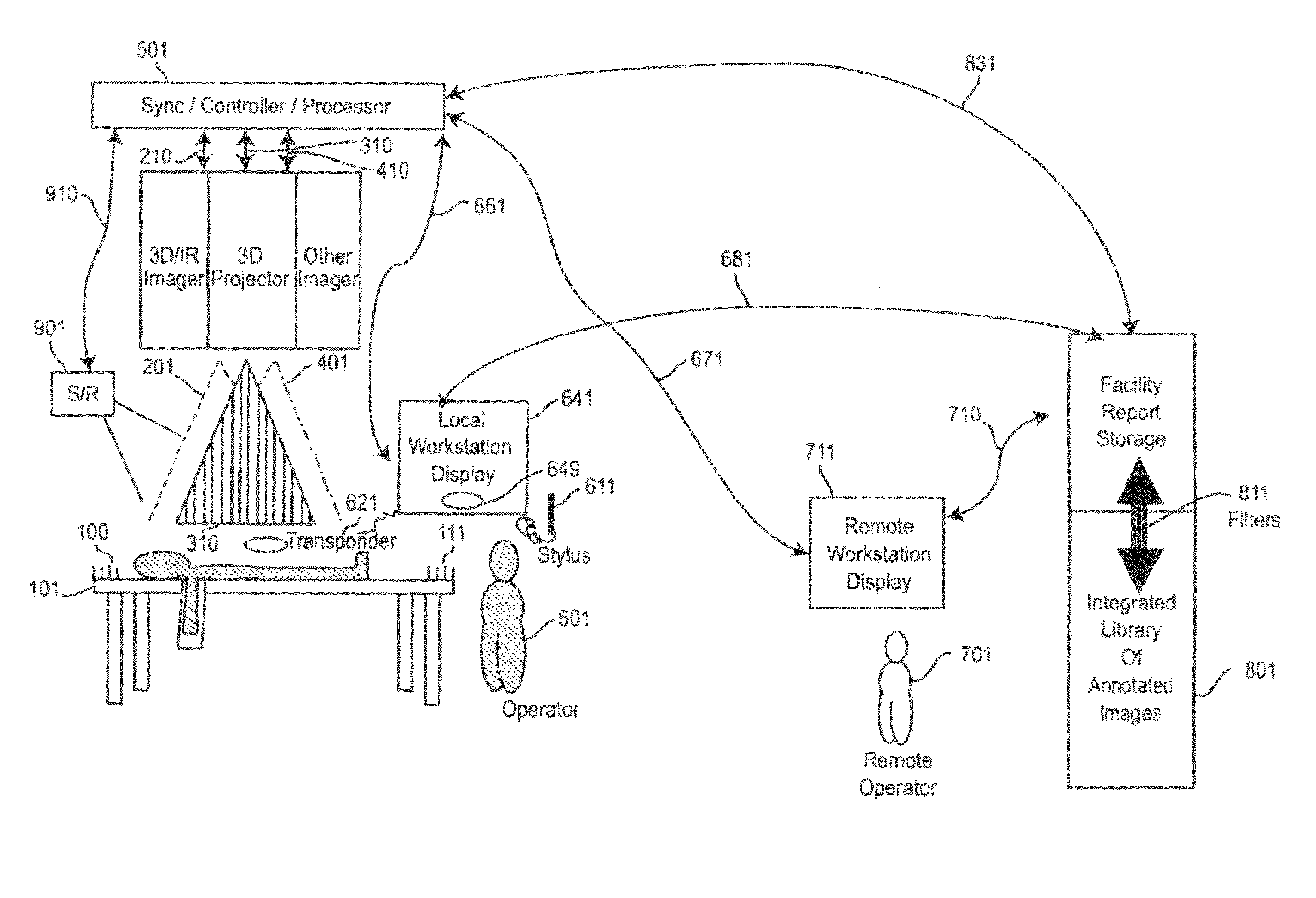
  • System and method for using three dimensional infrared imaging to provide detailed anatomical structure maps
  • System and method for using three dimensional infrared imaging to provide detailed anatomical structure maps
  • System and method for using three dimensional infrared imaging to provide detailed anatomical structure maps

Examples


case i

[0407, the Biometric System Selects the Identifying Area.

[0408]3D / IR / Visual imagery is collected of a broad area, such as a face, but only a sub-area is used for identification. The sub-area is selected by reference to landmarks that can be determined from one or more layers of the imagery. For example, a full facial profile image can be obtained. The selected sub-area can encompass a narrow swath extending from the mouth corner to the lower ear lobe, which is used to produce a thermal biometric signature. The curvilinear thermal features within that swath are determined along with their elevation contours. All or some of the features may be used for identification by matching against a database of previously extracted swath patterns. Anatomical structure information observable in the infrared swath images, such as blood vessels, moles, scars, lymph nodes, sweat glands, and wrinkles, can be used to precisely align enrollment and identification swaths. Standard pattern recognition te...

case ii

[0409 the Biometric Subject Selects Identifying Area

[0410]The subject can select any area of his body of appropriate size, and use it to produce his identifying biometric. No one else, and no component of the system, need be aware of what area of his body he selects. The total skin surface for an average size adult is on the order of 9 square meters. The portion that could be conveniently used for biometric identification using a handheld sensor in privacy includes the face, neck, hands, lower arms, legs and upper chest. There are different feature densities in the various areas. The required size of the sensor array is determined by the spatial resolution of the sensor detectors, their sensitivity, and the size population to be uniquely identified. For a small area of the skin, elevation can be assumed constant and the sensor can employ means to maintain a constant distance between sensor and skin. Therefore, a 2D / IR sensor array can be used for static imaging or a 1D array can be ...


PUM


Abstract

Calibrated infrared and range imaging sensors are used to produce a true-metric three-dimensional (3D) surface model of any body region within the fields of view of both sensors. Curvilinear surface features in both modalities are caused by internal and external anatomical elements. They are extracted to form 3D Feature Maps that are projected onto the skin surface. Skeletonized Feature Maps define subpixel intersections that serve as anatomical landmarks to aggregate multiple images for models of larger regions of the body, and to transform images into precise standard poses. Features are classified by origin, location, and characteristics to produce annotations that are recorded with the images and feature maps in reference image libraries. The system provides an enabling technology for searchable medical image libraries.

Description

[0001]This application claims the benefit of U.S. Provisional Application No. 60 / 923,764 titled “SYSTEM AND METHOD TO STANDARDIZE MEDICAL IMAGES” filed on Apr. 17, 2007.BACKGROUND OF THE INVENTION[0002]1. Field of the Invention[0003]The present invention generally relates to the use of infrared imaging and, in particular, to the use of three dimensional infrared anatomical imaging to provide detailed anatomical structure maps.[0004]2. Background Description[0005]Standardized Medical Imaging[0006]Imaging Sensor Technologies[0007]Several medical imaging technologies are in common use:[0008]X-ray images such as from mammographs and chest X rays are produced from X rays passing through and being attenuated by the patient's body tissues to produce a 2D projection image. The density at a point in the image represents the tissue densities through which the x-rays passed. X-ray imagery shows bone structure and fatty tissue[0009]Computed Tomography (CT) or Computed Axial (Computer Assisted) ...

Claims


Application Information

Patent Timeline
Patent Type & Authority Patents(United States)
IPC IPC(8): G06K9/00
CPCA61B5/0064A61B5/1077A61B5/411A61B5/415A61B5/418G06T7/0012G06F19/321G06Q50/22A61B5/015A61B5/0086G01K13/002A61B5/7264A61B5/4519G16H30/40G16H30/20Y02A90/10A61B5/445G01K13/20
Inventor PROKOSKI, FRANCINE J.
Owner PROKOSKI FRANCINE J
Learn More