
Cellular honeycomb hybrid capacitors with non-uniform cell geometry

a hybrid capacitor and honeycomb technology, applied in the field of hybrid capacitors, can solve the problems of low energy and power density of hybrid capacitors known today, and achieve the effect of improving energy density and power density

Inactive Publication Date: 2013-06-04
CORNING INC
View PDF4 Cites 0 Cited by
  • Summary
  • Abstract
  • Description
  • Claims
  • Application Information

AI Technical Summary

Benefits of technology

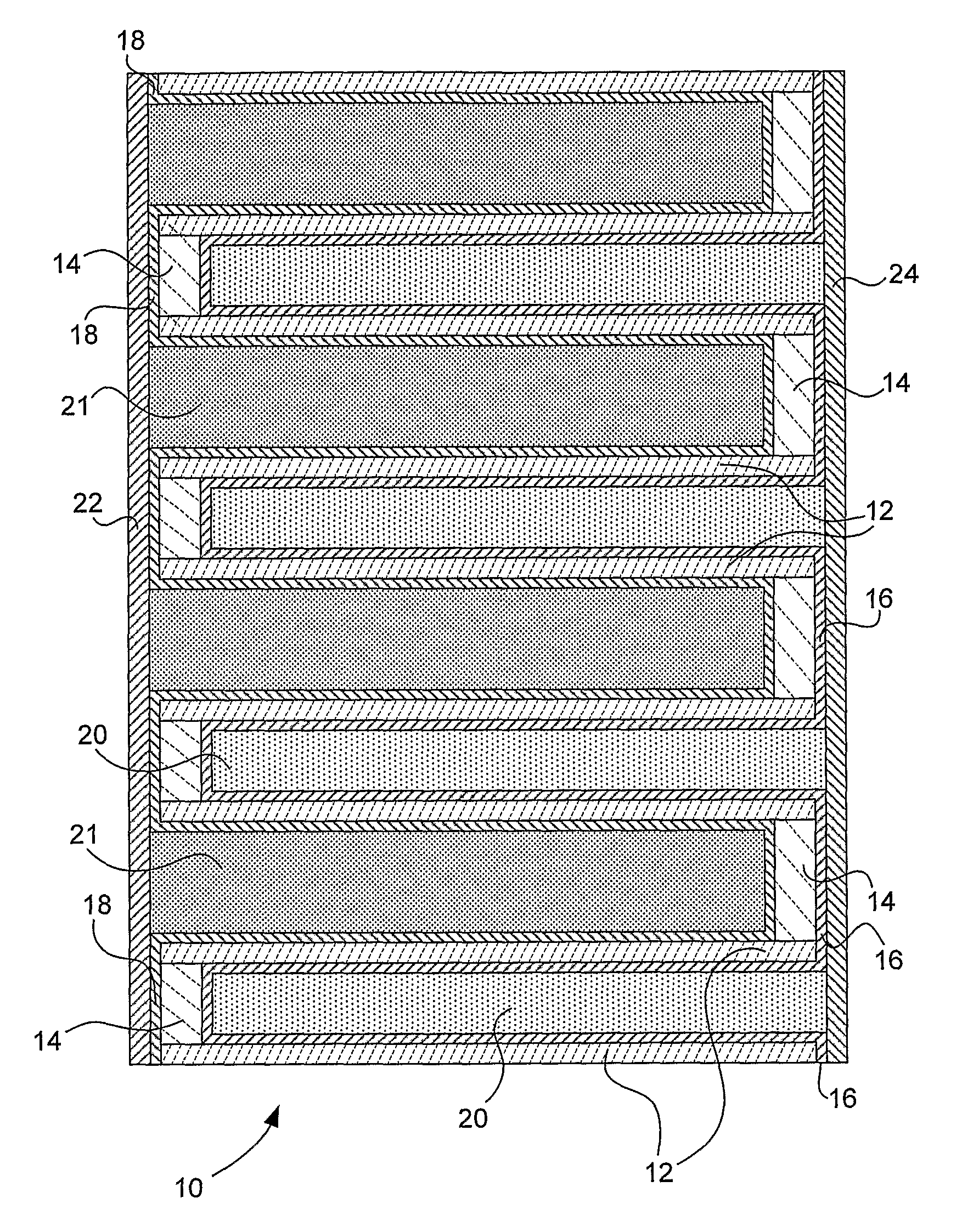
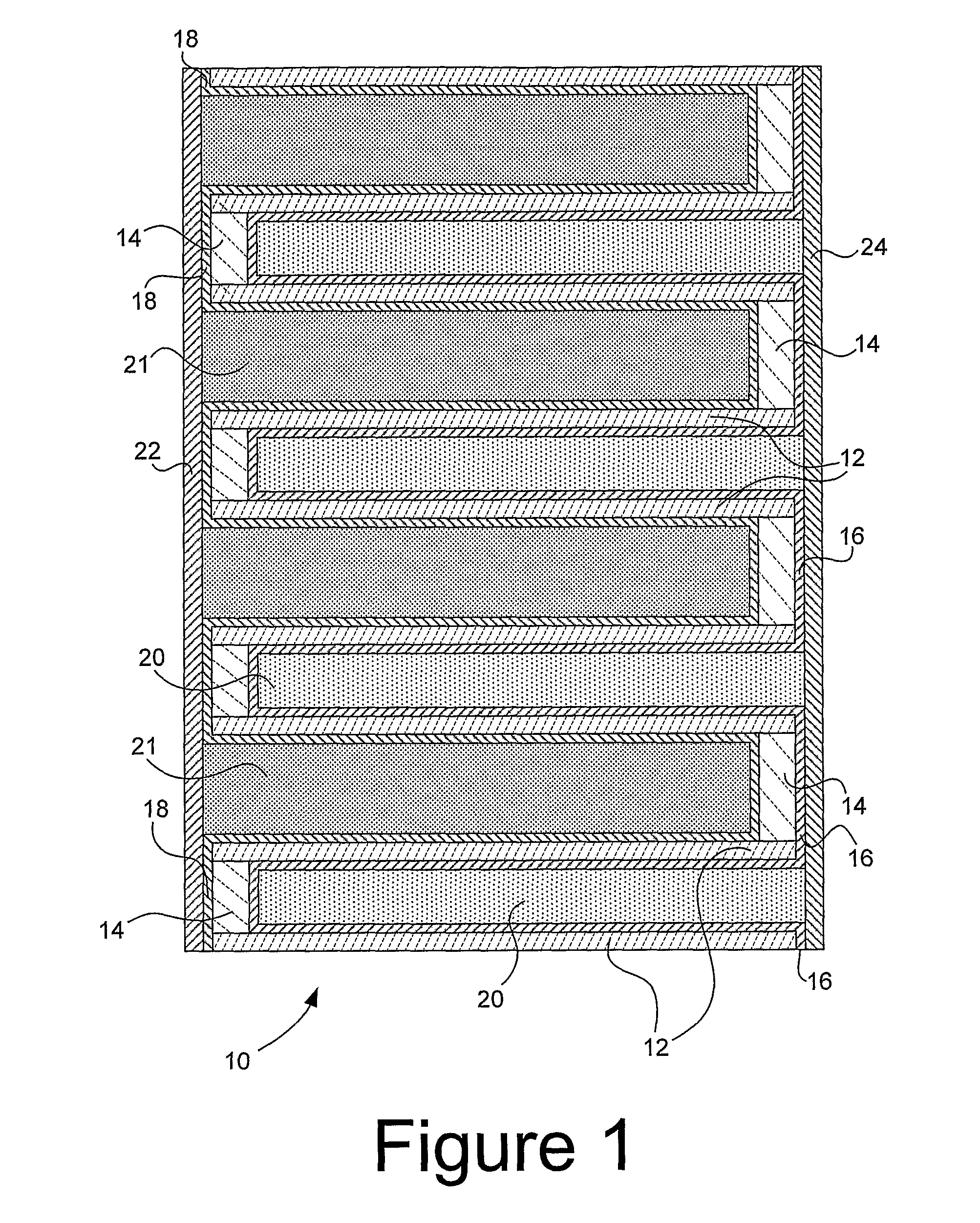
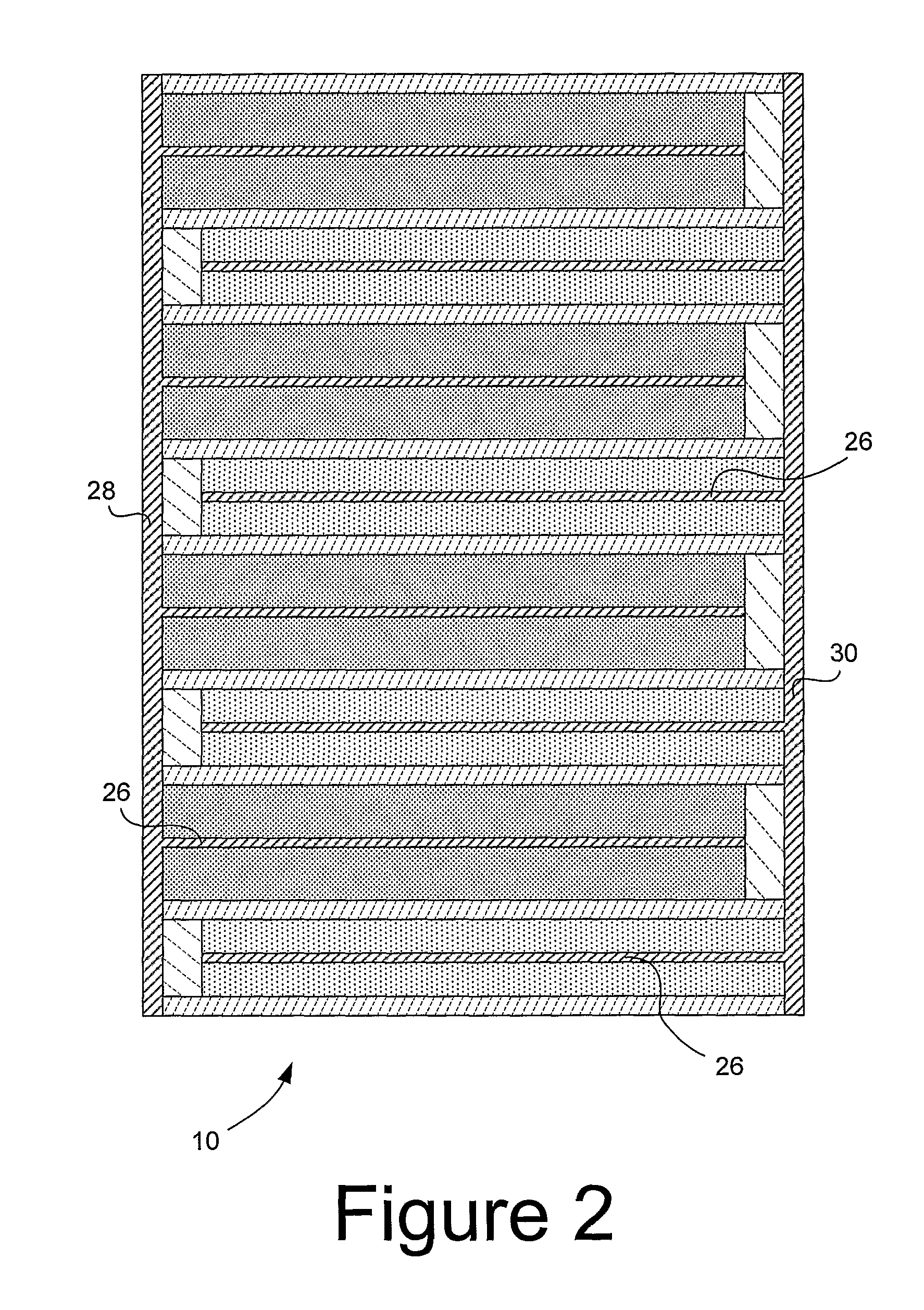
This patent describes an ultracapacitor device that includes a porous honeycomb structure with cells of non-uniform geometry and optimized for use with a specific chemistry. The size and size differences of the cells are optimized for performance. The honeycomb structure is made of a stable material, such as cordierite or silicon nitride, and has high-surface-area electrodes and a conductive layer on its inner surface. The device also has a thin and flexible electrolyte in contact with the electrodes. The invention provides methods for making the device. The technical effects of the patent are optimized performance and a flexible, efficient ultracapacitor device that can be processed at high temperatures and has high-surface-area electrodes.

Problems solved by technology

The energy and power density of hybrid capacitors known today is not as high as would be generally desired for various applications, including hybrid vehicles.

Method used


Image

  • Cellular honeycomb hybrid capacitors with non-uniform cell geometry
  • Cellular honeycomb hybrid capacitors with non-uniform cell geometry
  • Cellular honeycomb hybrid capacitors with non-uniform cell geometry

Examples


example 1

[0057]Experiments were carried out to demonstrate certain capabilities of metal coating on honeycomb walls. Colloidal silver was coated on a 600 cell per square inch (186 cell per square cm) 4 mil (100 micron) wall cordierite honeycomb structure via dip coating. This particular honeycomb had 40% porosity in the walls. The honeycomb walls were thoroughly coated with an electrically continuous coating of silver. Most importantly, fracture surface of the honeycomb showed that there was no penetration of silver particles in the honeycomb pore structure, indicating that this is a feasible approach to metal coating. FIG. 10 is a scanning electron microscope (SEM) backscattered electron image of a polished cross-section of an intersection within the resulting coated honeycomb structure, taken at a magnification of 250×, and showing the honeycomb material 36, the pores within the honeycomb material 38, and the silver layer 40 deposited on the surface of the honeycomb material 36 but not in ...

example 2

[0058]Aluminum was thermally evaporated onto a cordierite honeycomb structure with dimensions of 600 cells per square inch (186 cells per square cm), 4 mil (100 micron) wall. An excellently adherent coating of aluminum was obtained on the walls. Porosity of the coating was demonstrated via a water drop test.

example 3

Ultracapacitor Experiment

[0059]A cordierite honeycomb sample with cell dimensions of 600 cells per square inch (186 cells per square cm) and 4 mil (100 micron) wall thickness, and with a wall porosity of 40% and pore size of 3-5 microns, was obtained. A pin array of nickel electrodes was fabricated by chemical etching of nickel sheet or foil. The resulting array was sealed to the honeycomb from one end with a silicon resin (Dow Corning Sylgard 186). The cells with the pins were then filled with a activated carbon 80% wt, PVDF 10% wt, and carbon black 10% wt paste in acetone. After the cells were filled and dried a very compact and strong structure was formed around the pins. After drying open ends of the cells were capped with the silicone resin. The procedure was repeated with the other end of the sample. The end of the pin arrays protruding from either end of the sample were connected together to form positive and negative terminals for the capacitor. Electrolyte was then introduc...


PUM

PropertyMeasurementUnit
temperatureaaaaaaaaaa
temperaturesaaaaaaaaaa
wall thicknessaaaaaaaaaa

Abstract

A hybrid capacitor includes an electrically non-conductive rigid or semi-rigid porous honeycomb structure having cells extending along a common direction, the cells having a plurality of cross-sectional shapes. The honeycomb structure is desirably formed of a material that is stable at temperatures of 300° or more, such that high temperature processing can be used to help ensure high purity of the final product. The material of the structure may desirably be an oxide or non-oxide ceramic, such as cordierite, silicon nitride, alumina, aluminum titanate, zircon, glass, or glass-ceramic. The plurality of shapes of the cells includes larger shapes in which cells are disposed non-galvanic electrodes, with galvanic electrodes disposed in cells of other shapes.

Description

BACKGROUND OF THE INVENTION[0001]1. Field of the Invention[0002]The present invention relates generally to hybrid capacitors, and particularly to high energy density and high power density hybrid capacitors employing cellular honeycombed separator structures with non-uniform cell geometry, and to methods for producing the same.[0003]2. Technical Background[0004]Ultracapacitors, also commonly referred to as electric double layer capacitors, are potentially useful for many applications where pulse power or power leveling is desirable or required. These applications range from small devices such as cell phones to large devices such as hybrid vehicles.[0005]Where a device having power densities similar to an ultracapacitor but with increased energy density is desired, hybrid capacitors have been explored. In an ultracapacitor as used herein, the electrodes are non-galvanic, meaning that they do not undergo faradaic reactions in the associated electrolyte solution within the intended ope...

Claims


Application Information

Patent Timeline
Patent Type & Authority Patents(United States)
IPC IPC(8): H01G9/00
CPCH01G9/016H01G9/058H01G9/14H01G9/155H01G11/02H01G11/04H01G11/52H01G11/72H01G11/78H01G11/12Y10T29/417Y02E60/13Y02T10/7022Y02T10/70H01G9/00H01G11/22H01G11/74
Inventor BOURCIER, ROY JOSEPHGADKAREE, KISHOR PURUSHOTTAMPATIL, MALLANAGOUDA DYAMANAGOUDASHENG, HUAN-HUNGSOULLIERE, MARK J.
Owner CORNING INC
Learn More