Core block, and magnetic pole core using core blocks for motor
a technology of core blocks and core blocks, applied in the direction of magnetic circuit rotating parts, dynamo-electric machines, magnetic circuit shapes/forms/construction, etc., can solve the problems of difficulty in winding, difficulty in increasing the space factor of winding, and hindering the improvement of motor performance, so as to achieve simple connection structure of adjacent core blocks and high space factor
- Summary
- Abstract
- Description
- Claims
- Application Information
AI Technical Summary
Benefits of technology
Problems solved by technology
Method used
Image
Examples
first embodiment
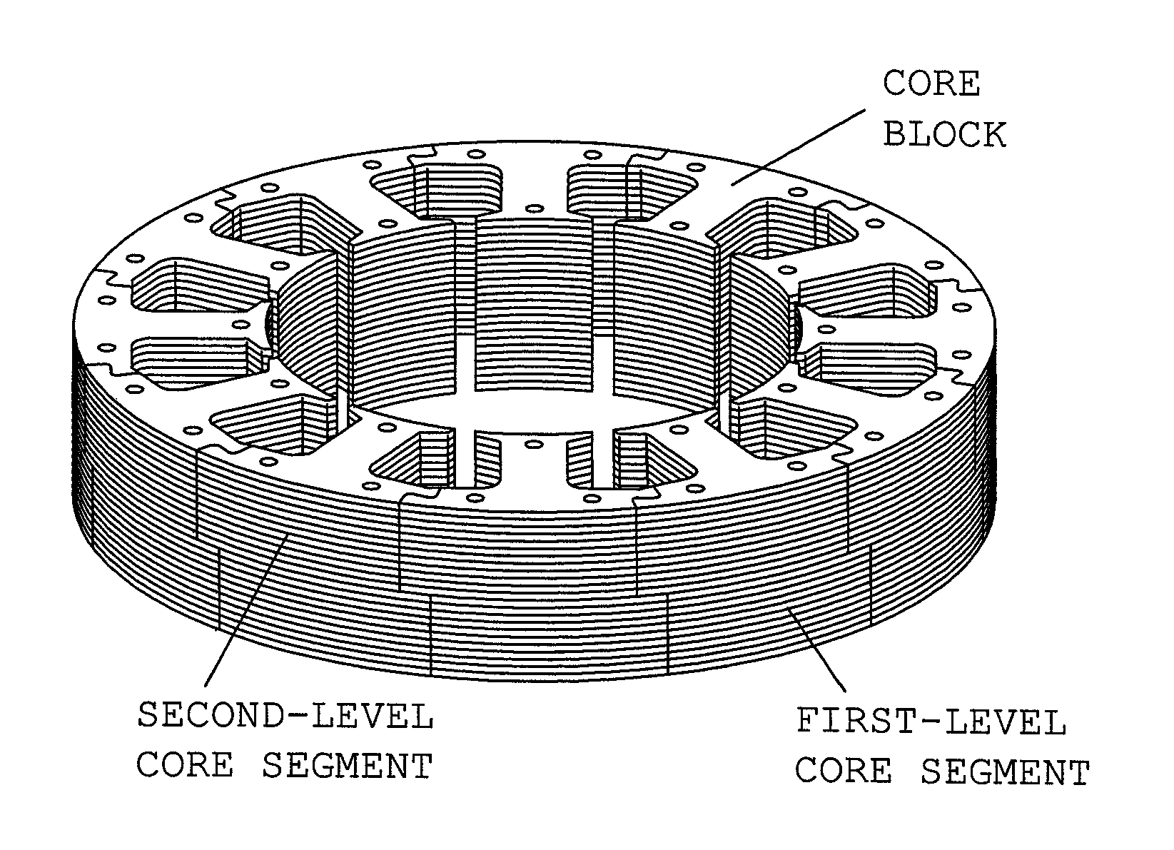
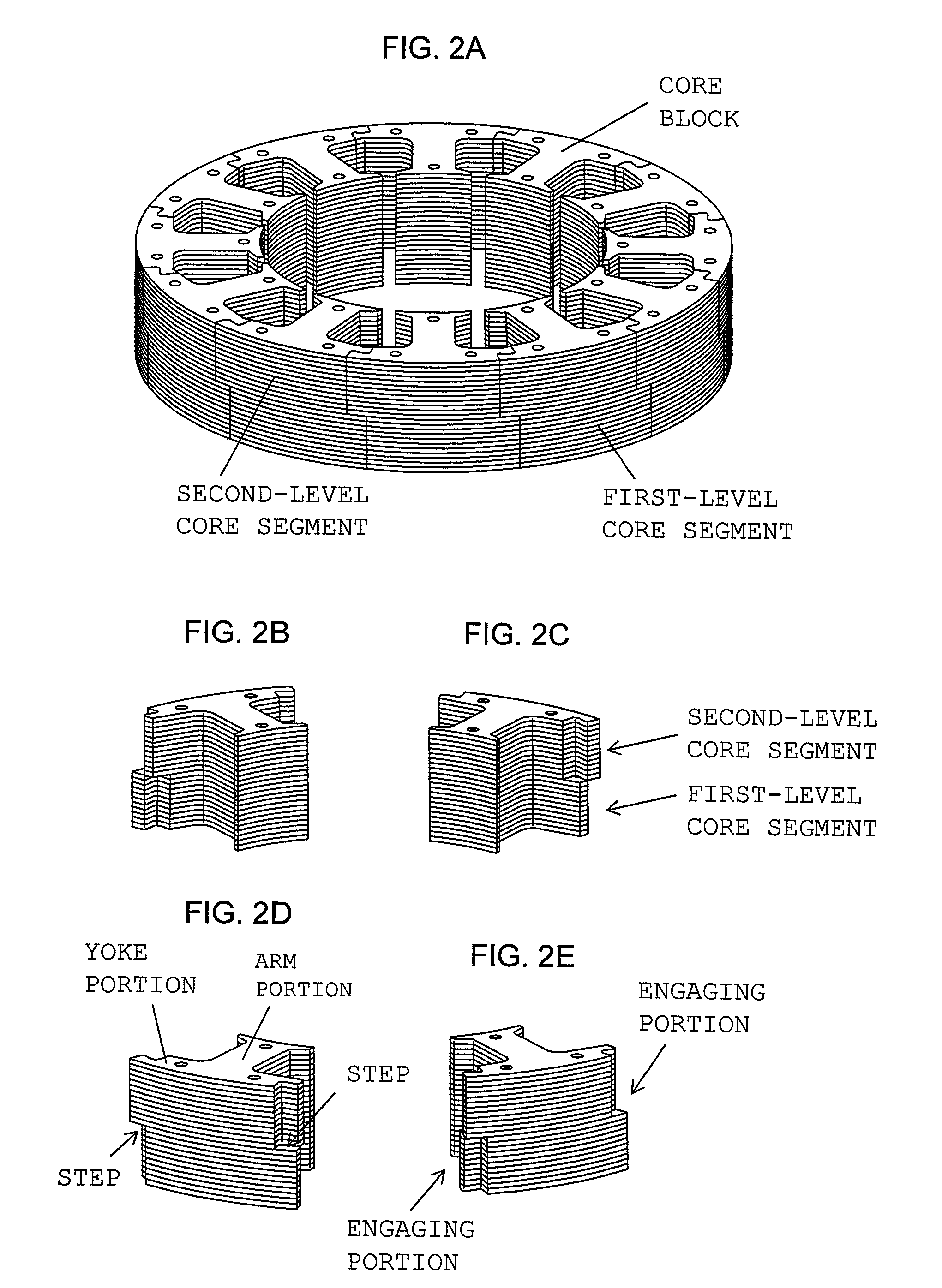
[0053]FIGS. 2A to 2E are views showing a stator core according to the present invention employed in the motor of FIG. 1. FIG. 2A is a perspective view showing an assembly of core blocks. FIGS. 2B to 2E are perspective views of a single core block as viewed from different directions. In actual practice, winding is performed on the individual core blocks which have undergone insulation treatment; then, the core blocks are fixedly joined together. However, for convenience of explanation, in FIG. 2 and the drawings appearing in the following description, the illustration of insulation treatment and winding is omitted. The insulation treatment and winding can be performed by use of known techniques.
[0054]The illustrated stator core is an assembly of 12 core blocks (12 poles) of the same shape. Each of the core blocks is configured such that core segments are stacked in two levels in the axial direction of the rotative shaft. A first-level core segment and a second-level core segment do n...
sixth embodiment
[0069]FIG. 11 is a perspective view of a single core block of a stator core according to the present invention. In the stator core, a single core block is configured such that three arm portions A to C are formed integral with a single arcuate yoke portion. In formation of, for example, the annular stator core (12 poles) shown in FIG. 2A, four core blocks (each having 3 poles) shown in FIG. 11 are connected. Engaging portions are provided at opposite ends of the yoke portion integrated with the three arm portions A to C. In the case where particular difficulty is not encountered in winding work as in winding of a thin wire, use of core blocks of the illustrated configuration is advantageous from the viewpoint of improvement of utilization of core material and a reduction in the number of man-hours required for engagement of core blocks. The present embodiment has been described while mentioning a core block configured such that three arm portions (3 poles) are integrated with a sing...
seventh embodiment
[0070]FIGS. 12A and 12B are views showing core blocks of different types of a stator core according to the present invention. FIGS. 12A and 12B are perspective views showing a core block of type A and a core block of type B, respectively. Both core blocks of type A and type B are symmetric. In the core block of type A, the second-level core segment has radially outer protrusions protruding from circumferentially opposite sides thereof, and the first-level core segment has radially inner protrusions protruding from circumferentially opposite sides thereof. The core block of type B is in reverse relation with that of type A; specifically, the first-level core segment has radially outer protrusions protruding from circumferentially opposite sides thereof, whereas the second-level core segment has radially inner protrusions protruding from circumferentially opposite sides thereof. Needless to say, the protrusions are accompanied by respective recesses. Similar to the above-described emb...
PUM
 Abstract
Description
Claims
Application Information
 - R&D
- Intellectual Property
- Life Sciences
- Materials
- Tech Scout
- Unparalleled Data Quality
- Higher Quality Content
- 60% Fewer Hallucinations
Browse by: Latest US Patents, China's latest patents, Technical Efficacy Thesaurus, Application Domain, Technology Topic, Popular Technical Reports.
© 2025 PatSnap. All rights reserved.Legal|Privacy policy|Modern Slavery Act Transparency Statement|Sitemap|About US| Contact US: help@patsnap.com


