Particle beam treatment device and irradiation dose setting method of the particle beam treatment device
a treatment device and particle beam technology, applied in the field of particle beam treatment devices, can solve the problem of not being able to measure directly the dose of biology in the target volume tv during irradiation
- Summary
- Abstract
- Description
- Claims
- Application Information
AI Technical Summary
Benefits of technology
Problems solved by technology
Method used
Image
Examples
embodiment 1
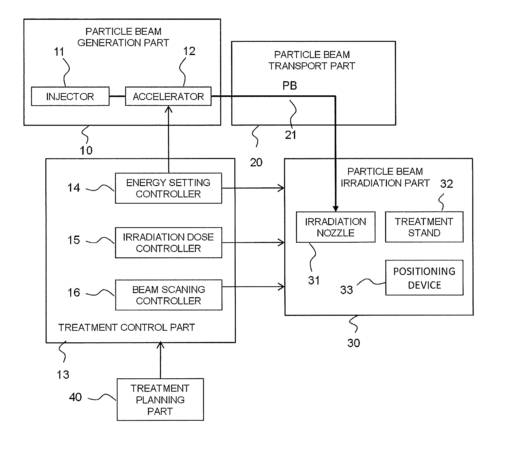
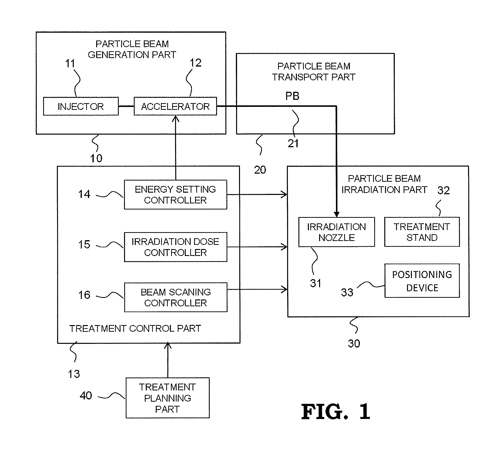
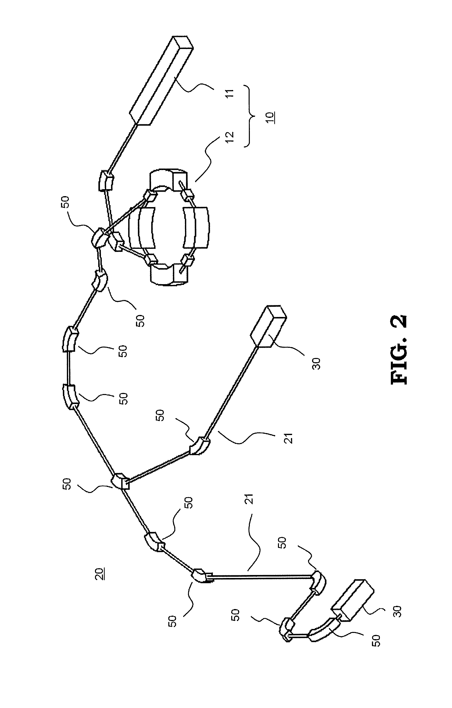
[0040]FIG. 1 is a block diagram schematically illustrating the configuration of a particle beam treatment device according to the present invention and FIG. 2 is a bird's-eye view schematically illustrating an example of whole configuration of a particle beam treatment device. As shown in FIGS. 1 and 2, the particle beam treatment device includes a particle beam generation part 10, a particle beam transport part 20, and two particle beam irradiation parts 30. FIG. 2 shows a particle beam treatment device having two particle beam irradiation parts, however, number of particle beam irradiation part is not limited to two, a particle beam treatment device having one particle beam irradiation part or three or more particle beam irradiation parts may be acceptable. For simplification, FIG. 1 shows a particle beam treatment device having one particle beam irradiation part. For reasons of application of radiation safety management and the like, the particle beam generation part 10 and the p...
embodiment 2
[0050]FIGS. 6 to 10 are diagrams for describing the details of operation of a particle beam treatment device according to EMBODIMENT 2 of the present invention, that is, acquisition and storing of radiation source basic data in the step ST1 shown in FIG. 5. FIG. 6 is an outline configuration diagram showing a device used in a first step in EMBODIMENT 2. In FIG. 6, the same symbol shows a part which is same as that in FIG. 1 or a corresponding part. A water phantom 60 is irradiated with a pencil beam P having a predetermined beam diameter which is emitted from an irradiation nozzle 31, without scanning the pencil beam P in the X or the Y direction. A dose sensor 341 comprising an ion chamber is arranged between the irradiation nozzle 31 and the water phantom 60. A parallel board-type chamber 61 is provided, to be movable at a part of the water phantom 60 which is irradiated with the pencil beam P, in the advancing direction of the pencil beam P, that is, the Z direction. The charge a...
embodiment 3
[0057]FIGS. 11 to 13 are diagrams for describing the details of operation of a particle beam treatment device in EMBODIMENT 3 of the present invention, that is, acquisition and storing of basic data of the spot scanning irradiation which is the operation in the step ST2 shown in FIG. 5. FIG. 11 is an outline configuration diagram showing a main part of a particle beam treatment device used in EMBODIMENT 3. In the step ST2, a pencil beam P is scanned, and the absorbed dose data is acquired by a thimble chamber 62 which is set at a predetermined position at the reference depth D0. FIG. 12 shows the image of the spot scanning irradiation which is performed on a surface of the reference depth in this measurement. When this measurement is performed, the condition to make the dose distribution at a part in the reference depth (plato), which is applied by the irradiation for one slice, that is, by irradiation with a certain energy, uniform is obtained. On this occasion, this measurement is...
PUM
 Abstract
Description
Claims
Application Information
 - R&D
- Intellectual Property
- Life Sciences
- Materials
- Tech Scout
- Unparalleled Data Quality
- Higher Quality Content
- 60% Fewer Hallucinations
Browse by: Latest US Patents, China's latest patents, Technical Efficacy Thesaurus, Application Domain, Technology Topic, Popular Technical Reports.
© 2025 PatSnap. All rights reserved.Legal|Privacy policy|Modern Slavery Act Transparency Statement|Sitemap|About US| Contact US: help@patsnap.com


