
Multimode filter architecture

a filter architecture and multi-mode technology, applied in the field of signal processing, can solve the problems of less support for all broadcast standards, fewer challenges for transmission and receiver equipment makers, and the requirement of conversion tuner configuration to provide a high level of image rejection with this tuner configuration, so as to improve image rejection, reduce the number of components, and improve the effect of image rejection

Inactive Publication Date: 2013-04-09
CSR TECH INC
View PDF18 Cites 2 Cited by
  • Summary
  • Abstract
  • Description
  • Claims
  • Application Information

AI Technical Summary

Benefits of technology

The solution provides a highly integrated and flexible receiver configuration that supports multiple broadcast standards with low noise figures and linearity across a broad frequency band, reducing component count and enhancing performance by mitigating image rejection and spurs, thus facilitating a high level of integration and efficient signal processing.

Problems solved by technology

The use of these varied broadcast standards has presented challenges for the makers of transmission and receiver equipment.
In particular, it is a challenge for manufacturers to support both an existing analog broadcast standard as well as a digital broadcast standard, much less support all such broadcast standards.
Moreover, images associated with the use of the multi-conversion tuner configuration demand a high level of image rejection be provided with this tuner configuration.
Thus it can be appreciated that the receiver configuration is not well suited to a high level of integration or simplification.
These filters and their attendant selection circuitry provide a receiver configuration even less suited to a high level of integration that illustrated in FIG. 1.
Past efforts to create a flexible receiver solution have resulted in unsatisfying architectures which sacrifice performance for lower cost and reduced power consumption.
Performance issues such as dynamic range and channel cross modulation are symptoms of low power operation combined with inadequate architecture.
Moreover, such solutions have required large blocks of software code to be uploaded to the tuner before operation with a given broadcast standard, thus providing undesirable deployment and initialization issues.

Method used


Image

  • Multimode filter architecture
  • Multimode filter architecture
  • Multimode filter architecture

Examples


Embodiment Construction

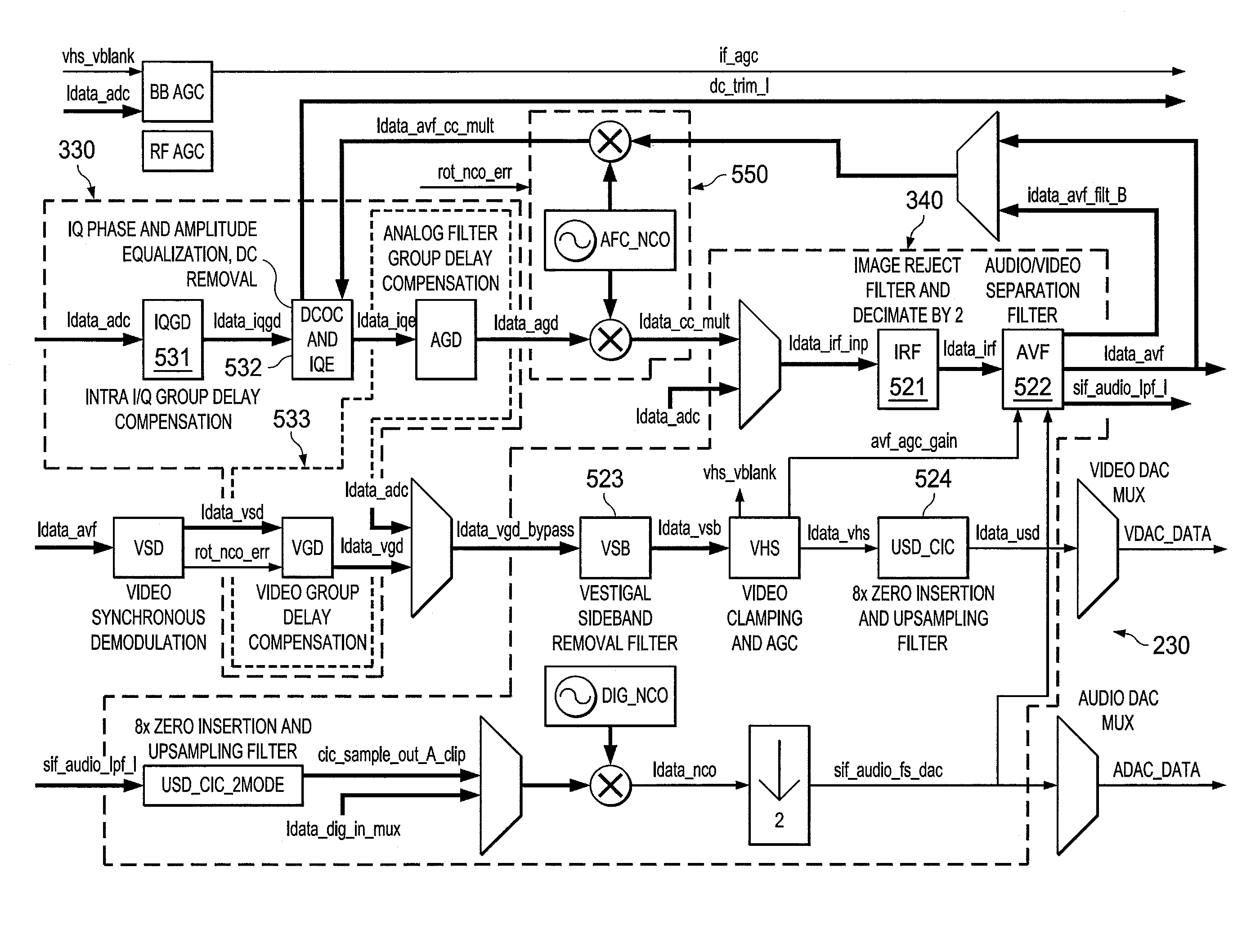
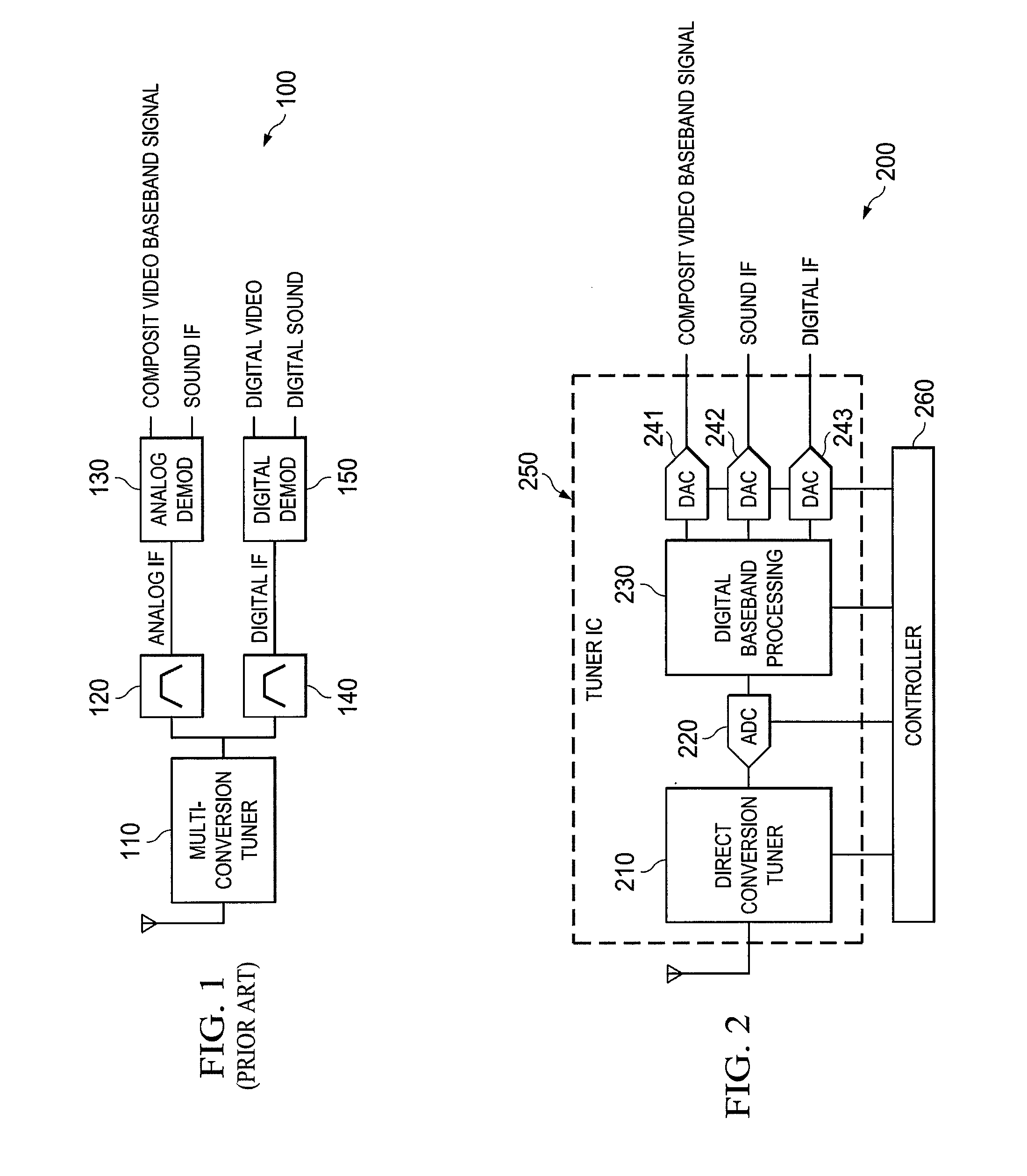
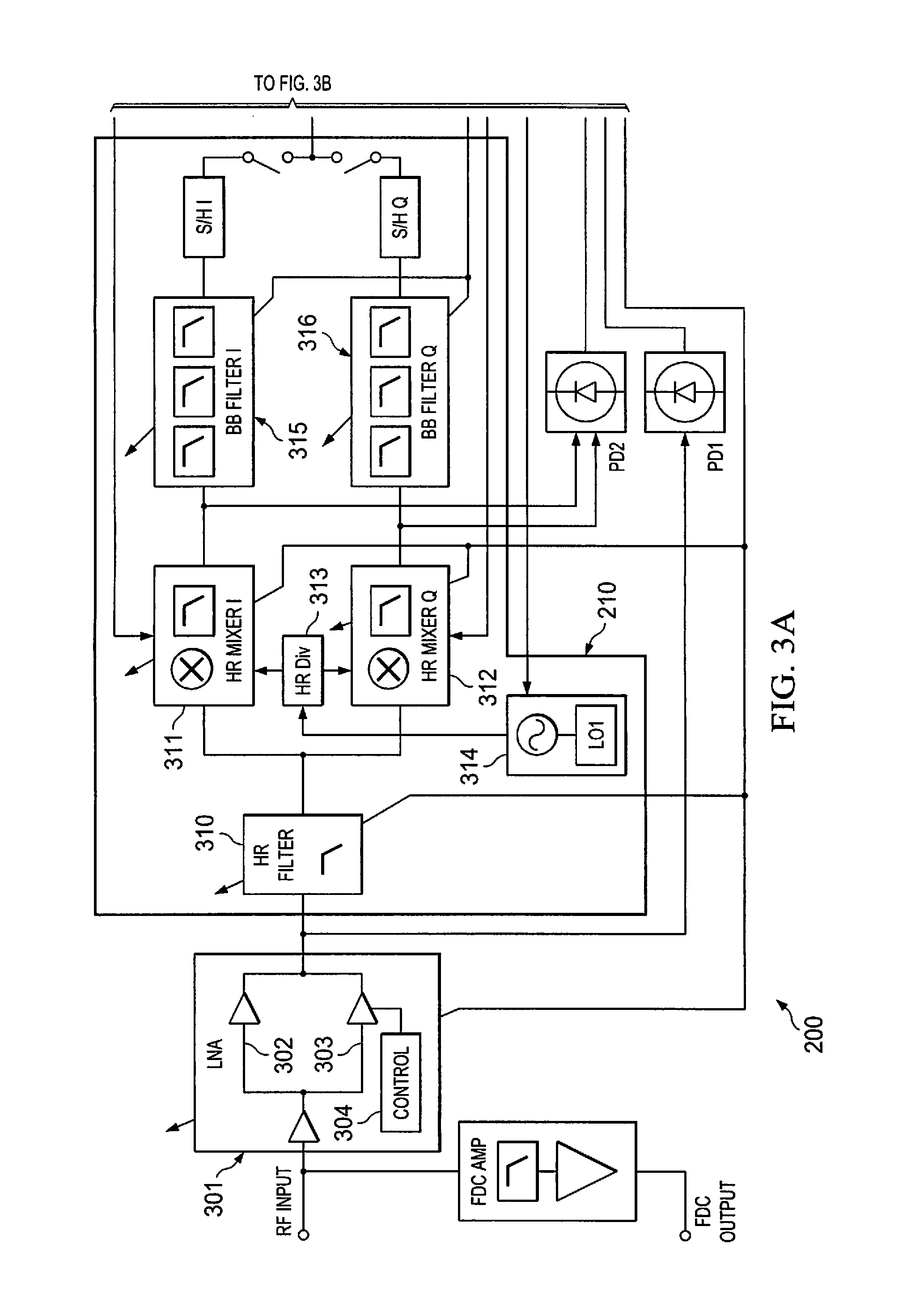
[0031]FIG. 2 shows a high level block diagram of a multimode direct conversion tuner architecture according to an embodiment of the invention. Multimode direct conversion tuner architecture 200 of the illustrated embodiment comprises direct conversion tuner 210, analog to digital converter (ADC) 221, digital baseband processing 230, and digital to analog converters (DACs) 241-243. Further, multimode direct conversion tuner architecture 200 of the illustrated embodiment includes controller 260 to control operation of direct conversion tuner 210, analog to digital converter (ADC) 221, digital baseband processing 230, and / or digital to analog converters (DACs) 241-243 as described herein. Controller 260 may comprise memory, input and output interfaces, a general-purpose processing unit (e.g., commercially available central processing unit (CPU)), operable under control of an instruction set (e.g., software, firmware, etc.), configured to provide and / or receive appropriate control signa...


PUM


Abstract

Systems and methods which provide a multimode tuner architecture implementing direct frequency conversion are shown. Embodiments provide a highly integrated configuration wherein low noise amplifier, tuner, analog and digital channel filter, and analog demodulator functionality are provided in a single integrated circuit. A LNA of embodiments implements a multi-path configuration with seamless switching to provide desired gain control while meeting noise and linearity design parameters. Embodiments of the invention implement in-phase and quadrature (IQ) equalization and a multimode channelization filter architecture to facilitate the use of direct frequency conversion. Embodiments implement spur avoidance techniques for improving tuner system operation and output using a clock signal generation architecture in which a system clock, sampling clock frequencies, local oscillator (LO) reference clock frequencies, and / or the like are dynamically movable.

Description

CROSS-REFERENCE TO RELATED APPLICATIONS[0001]The present application is related to concurrently filed and commonly assigned U.S. patent applications Ser. No. 12 / 632,624 entitled “Systems and Methods Providing In-Phase and Quadrature Equalization,” filed Dec. 7, 2009, Ser. No. 12 / 632,571 entitled Systems and Methods Providing Spur Avoidance in a Direct Conversion Tuner Architecture,” filed Dec. 7, 2012 and Ser. No. 12 / 632,648 entitled “Systems and Methods Providing Multi-Path Low Noise Amplifiers With Seamless Switching,” filed Dec. 7, 2012 the disclosures of which are hereby incorporated herein by reference.TECHNICAL FIELD[0002]The disclosure relates generally to signal processing and, more particularly, to a multi-mode filter architecture for use in signal processing.BACKGROUND OF THE INVENTION[0003]Television broadcast signals, both terrestrial and cable system transmission, have been provided in accordance with various standards. For example, the National Television System Commit...

Claims


Application Information

Patent Timeline
Patent Type & Authority Patents(United States)
IPC IPC(8): H04B1/10
CPCH04B1/001H04N5/455H04N5/46H04N21/42638H04N21/4382H04N21/6112
Inventor LAURENT-MICHEL, STEPHANESKULL, OLIVERDOAK, ALAN
Owner CSR TECH INC
Learn More