
Vertically separated pass through conveyor system and method in surface mount technology process equipment

a conveyor system and vertical separation technology, applied in the field of surface mount technology, can solve the problems of limiting the pass through capacity of the system, unable to easily adjust the lane size, and inability to dynamically sizing the conveyor track to handle different sizes of circuit boards

Inactive Publication Date: 2013-04-09
ILLINOIS TOOL WORKS INC
View PDF33 Cites 18 Cited by
  • Summary
  • Abstract
  • Description
  • Claims
  • Application Information

AI Technical Summary

Benefits of technology

The present patent is about a method and apparatus for depositing viscous material on electronic substrates. The technical effects of the patent include providing a method for processing electronic substrates by using a stencil printer with a transport system that can shuttle electronic substrates to and from a substrate support assembly, and a controller that can control the operation of the apparatus. The apparatus includes a frame, an assembly material applicator, and a substrate support assembly for securely supporting and sealing the electronic substrate in a material application position. The technical effects of the patent also include providing a method for loading electronic substrates onto a stencil printer in a different direction than another substrate, and performing inspection and other operations on the substrates.

Problems solved by technology

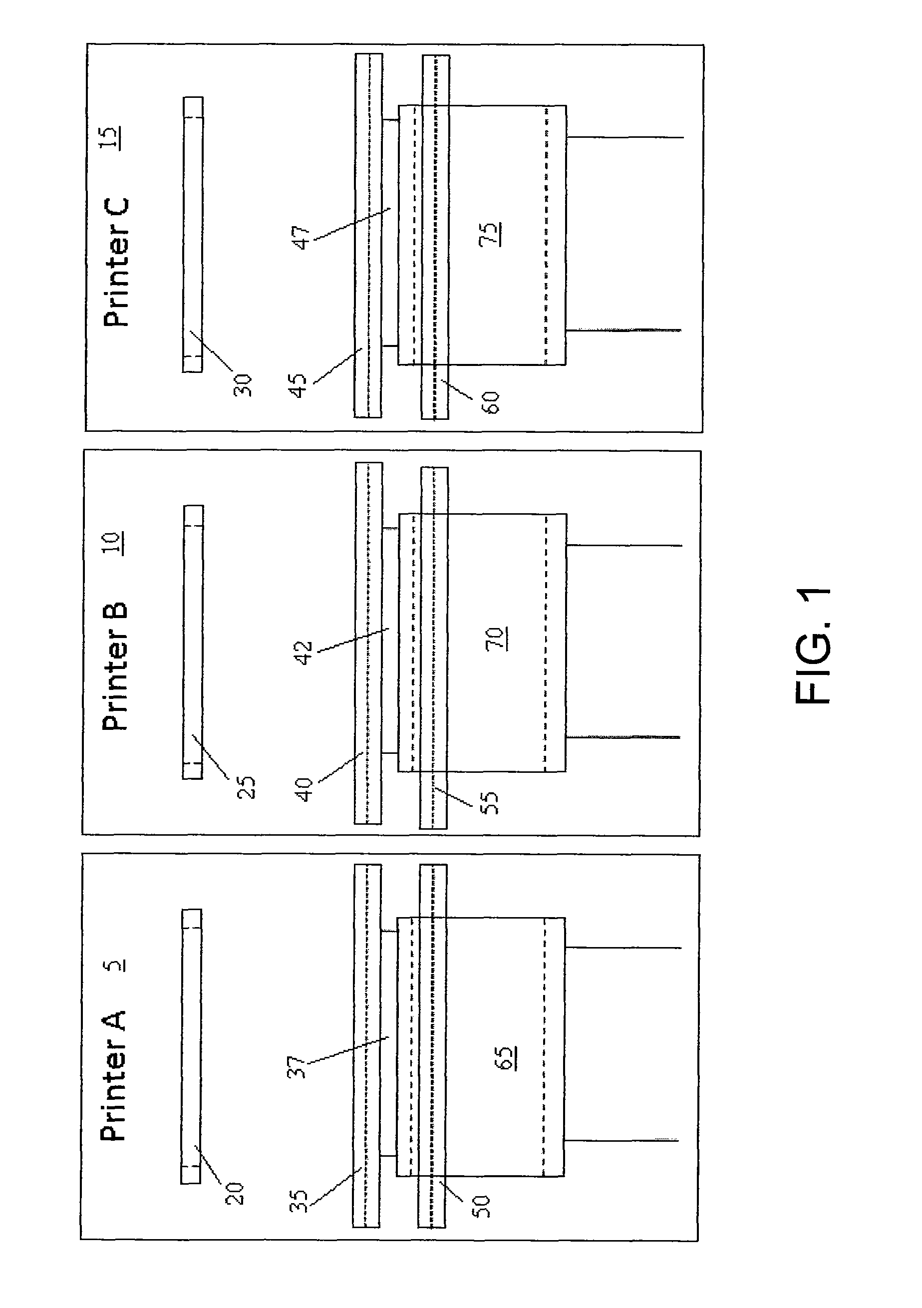
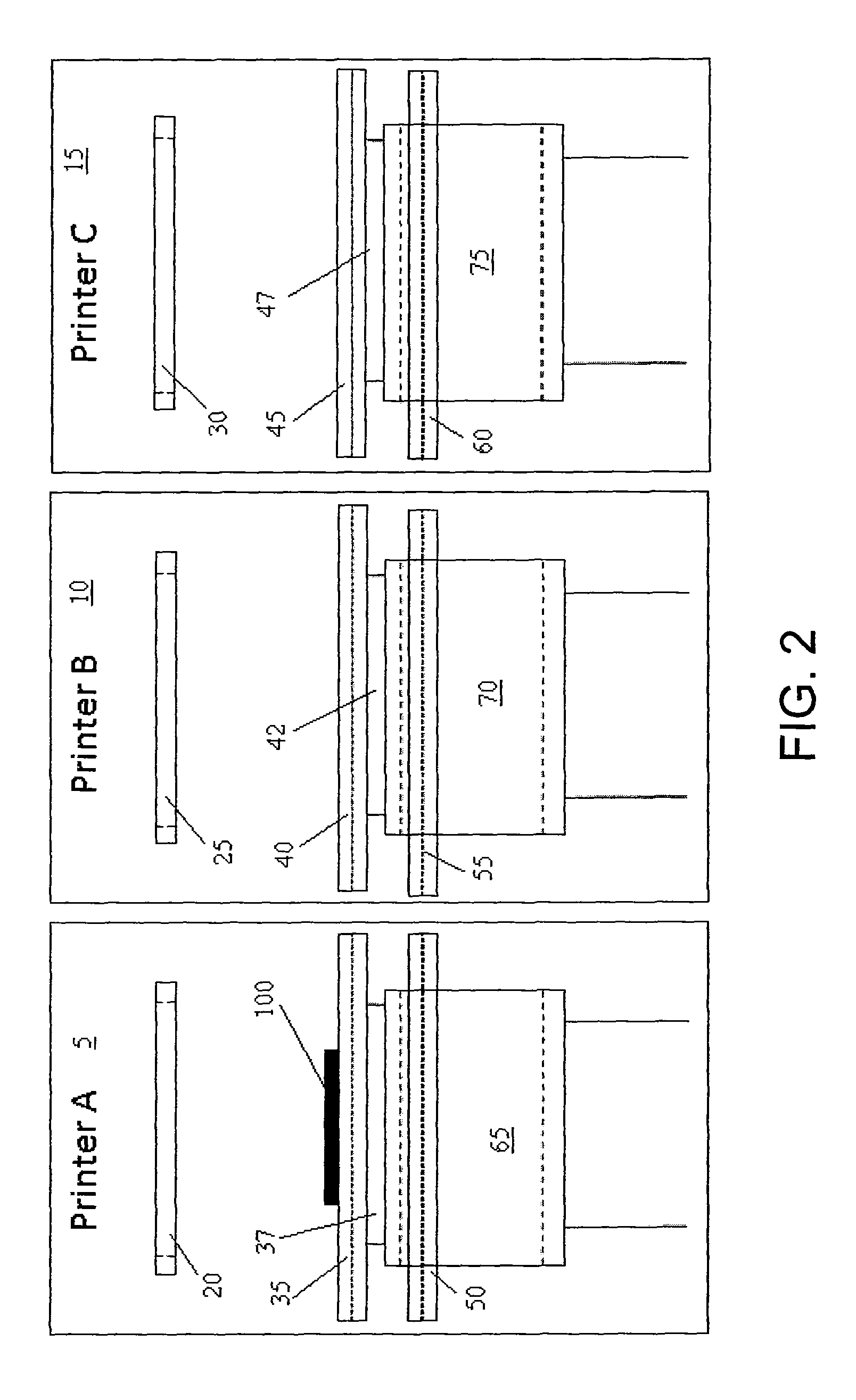
Dynamic sizing of conveyor tracks to handle different sizes of circuit boards may not be feasible on some dual-lane implementations because one practice is to use two printers in series and print one circuit board on the front lane of one machine and another circuit board on the rear lane of the other machine.
Because the print lanes typically use specific board tooling, the lane size cannot easily be adjusted.
This restriction limits pass through capacity of the system to the same size board or to a board size that is equal to or larger than the board being printed.
The placement machines are typically the more expensive equipment in the production line, and so effort is made to keep them operating at maximum capacity.
Errors discovered in the printing process may require manual intervention to rectify, which can impact the flow of materials into the placement system, decreasing the utilization of the placement system.

Method used


Image

  • Vertically separated pass through conveyor system and method in surface mount technology process equipment
  • Vertically separated pass through conveyor system and method in surface mount technology process equipment
  • Vertically separated pass through conveyor system and method in surface mount technology process equipment

Examples


Embodiment Construction

[0090]It should be understood that the disclosure is not limited in its application to the details of construction and arrangements of the components set forth herein. The disclosure is capable of other embodiments and of being practiced or carried out in various ways. Variations and modifications of the foregoing are within the scope of the present disclosure. It should also be understood that the material disclosed and defined herein extends to all alternative combinations of two or more of the individual features mentioned or evident from the text and / or the drawings. All of these different combinations constitute various alternative aspects of the present disclosure. The embodiments described herein explain the best modes known for practicing the disclosure and will enable others skilled in the art to utilize the disclosure.

[0091]The phraseology and terminology used herein is for the purpose of description and should not be regarded as limiting. The use of “including,”“comprisin...


PUM

PropertyMeasurementUnit
sizeaaaaaaaaaa
vertical travel lengthaaaaaaaaaa
viscousaaaaaaaaaa

Abstract

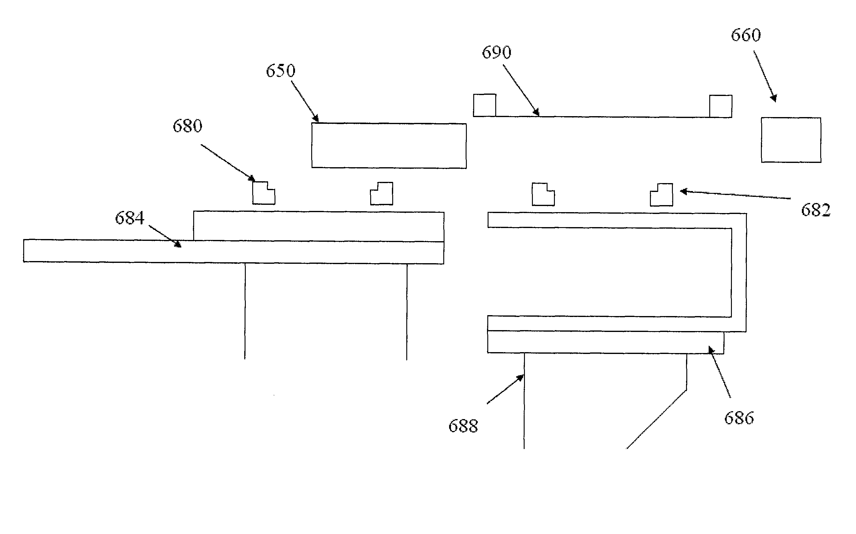
Disclosed herein is an apparatus for depositing viscous material on an electronic substrate. The apparatus comprises a frame, an assembly material applicator coupled to the frame and configured to apply assembly material to the electronic substrate, a substrate support assembly, coupled to the frame, configured to support and secure the electronic substrate in a print position, and a transport system, coupled to the frame, to shuttle electronic substrates to and from the substrate support assembly, the transport system including a first track and a second track, the first track being mounted on a first displacement mechanism and the second track being mounted on a second displacement mechanism configured to laterally move the second track relative to the first track, the second displacement mechanism configured to raise the first track relative to the second track.

Description

RELATED APPLICATIONS[0001]This application claims priority under 35 U.S.C. §119(e) to U.S. Provisional Application Ser. No. 61 / 115,954, entitled “SMALL FOOTPRINT STENCIL PRINTER CONCEPTS,” filed on Nov. 19, 2008, to U.S. Provisional Application Ser. No. 61 / 144,651, entitled “SMALL FOOTPRINT STENCIL PRINTER CONCEPTS,” filed on Jan. 14, 2009, to U.S. Provisional Application Ser. No. 61 / 176,797, entitled “DYNAMIC PASS-THROUGH LANE SIZING IN SURFACE-MOUNT TECHNOLOGY-SMT PROCESS EQUIPMENT,” filed on May 8, 2009, to U.S. Provisional Application Ser. No. 61 / 176,801, entitled “DEFECT REJECTION STATION IN SURFACE-MOUNT TECHNOLOGY-SMT PROCESS EQUIPMENT,” filed on May 8, 2009, to U.S. Provisional Application Ser. No. 61 / 176,803, entitled “ADJACENT PRINTER CONTROL IN SURFACE-MOUNT TECHNOLOGY-SMT PROCESS EQUIPMENT,” filed on May 8, 2009, to U.S. Provisional Application Ser. No. 61 / 176,804, entitled “PRINTER CONTROL OF ADJACENT EQUIPMENT IN SURFACE-MOUNT TECHNOLOGY-SMT PROCESS EQUIPMENT,” filed o...

Claims


Application Information

Patent Timeline
Patent Type & Authority Patents(United States)
IPC IPC(8): B41F15/18B05C13/00B05C11/02
CPCH05K13/0061B65G37/00H05K3/30H05K3/1216Y10T29/5313Y10T29/49126Y10T29/53187Y10T29/4913Y10T29/53174
Inventor DOYLE, DENNIS G.
Owner ILLINOIS TOOL WORKS INC
Learn More