
Vacuum sewage system

a sewage system and vacuum technology, applied in the direction of sewage draining, flushing devices, water closets, etc., can solve the problems of low degree of efficiency, large space requirements, and large solution requirements, and achieve the effect of reducing space requirements and effective sewage transportation

Active Publication Date: 2013-02-26
EVAC INT
View PDF26 Cites 3 Cited by
  • Summary
  • Abstract
  • Description
  • Claims
  • Application Information

AI Technical Summary

Benefits of technology

The invention provides a vacuum sewer system and a method for operating it that effectively pumps sewage with a pump arrangement that reduces space requirement. The system includes a vacuum tank, a vacuum pump, an on-line separator device, and two pump means: a liquid jet pump and a liquid pump connected to a circulation tank. The on-line separator device separates air from sewage and ensures that the vacuum pump does not pump liquid. The system allows for efficient pumping of non-homogenous sewage flow transported in the vacuum sewer piping, while also facilitating retro-fit installations in already existing vacuum sewage systems.

Problems solved by technology

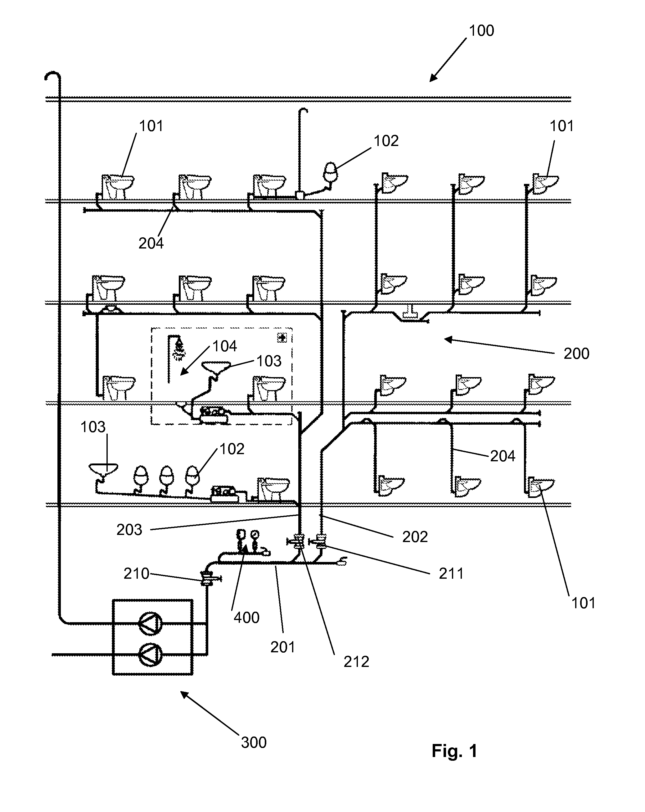
Due to the large volume collecting tank, such systems require a lot of space, which normally is not available in e.g. trains, marine vessels and aircraft.
This solution requires a lot of space.
Further, it has a low degree of efficiency.
This solution also requires a large space and furthermore the pump is very vulnerable to any humidity, thus requiring intricate control mechanisms.
The latter solutions with on-line pumps having the dual duty of generating vacuum by sucking air and simultaneously sucking sewage are, however, not very efficient.
Further, they are apt to functional disturbances.
The pumps used in this context are designed either for pumping air or pumping liquid, whereby the transport of both air and liquid generally is not very successful.
A large amount of air is sucked or forced into the vacuum sewer piping since the discharge valve remains open for a certain period of time.
Such a train of discrete slugs and air, especially in a ratio of about 1:30, which forms the sewage flow in a vacuum sewage system, is difficult to pump with high efficiency.

Method used


Image

  • Vacuum sewage system
  • Vacuum sewage system
  • Vacuum sewage system

Examples


first embodiment

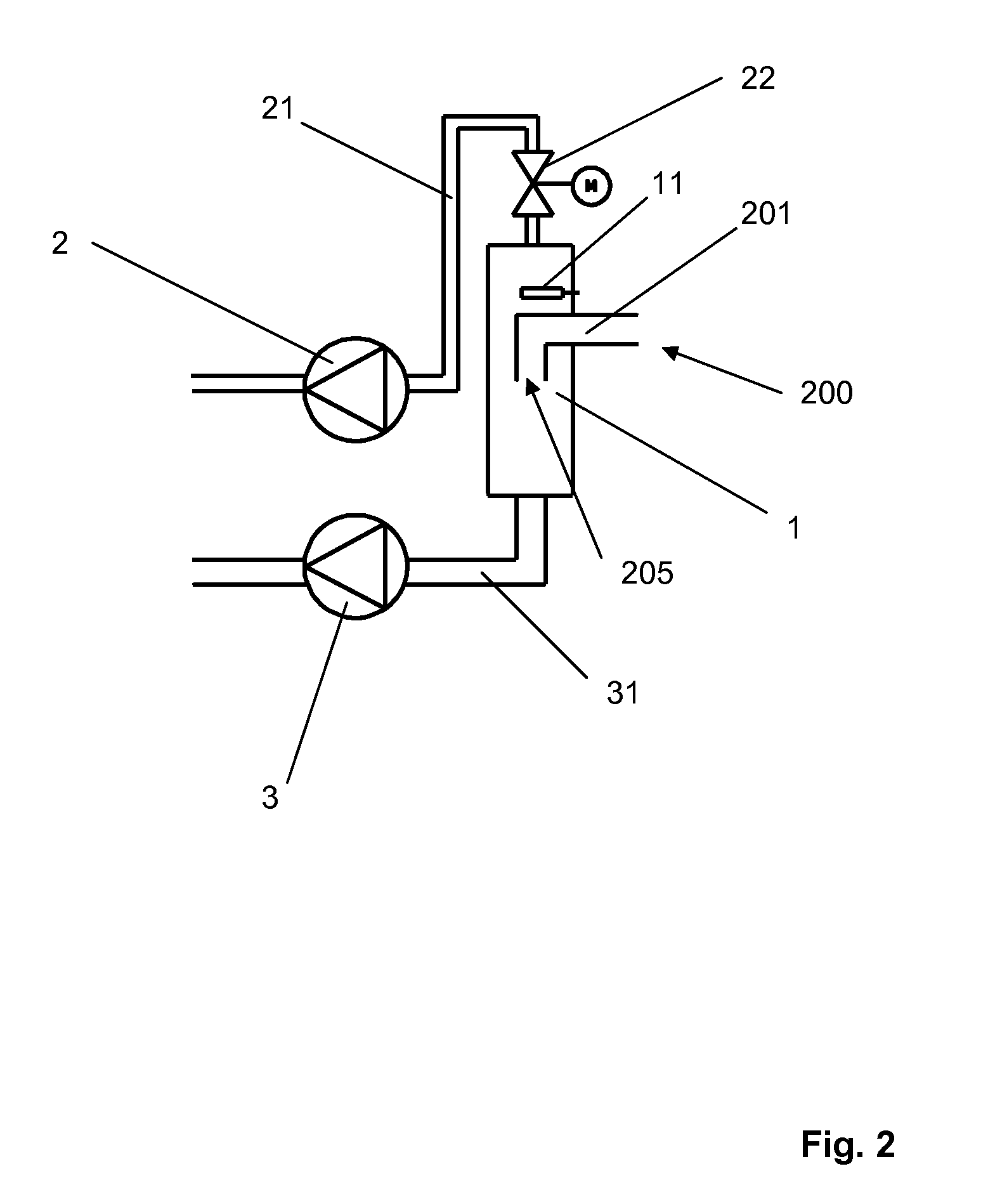
[0043]FIG. 2 shows the on-line separator device 1 with two pump means coupled in parallel to the on-line separator device 1. The first pump means 2 is a vacuum pump connected to the on-line separator device 1 by means of a conduit 21 provided with a first valve means 22, a shut-off valve, which is arranged on the suction side of the vacuum pump, between the vacuum pump and the on-line separator device 1. This first valve means 22 is not necessary for the appropriate functioning of the arrangement, but advantageous as a safety feature. The second pump means 3 is a liquid pump, which also should have the capacity to pump air, the suction side of which is connected to the on-line separator device 1 by means of a conduit 31. The two pump means are defined and discussed in more detail above.

[0044]The on-line separator device 1 is arranged in the vacuum sewer piping 200. With particular reference to FIG. 1, it is arranged in connection with the collector 201, whereby the sewage flow in th...

second embodiment

[0059]FIG. 3 shows the on-line separator device 1 with two pump means coupled in parallel to the on-line separator device 1. The first pump means 2 is a vacuum pump connected to the on-line separator device 1 by means of a conduit 21 provided with a first valve means 22, a shut-off valve, which is arranged on the suction side of the vacuum pump, between the vacuum pump and the on-line separator device 1. The second pump means 3 is connected to the on-line separator device 1 by means of a conduit 31. The second pump means 3 comprises a liquid jet pump 32 and a liquid pump 36 connected to a circulation tank 38. The liquid collected in the circulation tank 38 is circulated by the liquid pump 36 to the liquid jet pump 32 in order to produce a suction effect in the conduit 31 for pumping mainly sewage from the sewage flow flowing into the on-line separator device 1 and further into the circulation tank 38. The second pump means 3 corresponds to an ejector system. The two pump means are d...


PUM


Abstract

The invention relates to a vacuum sewage system, which includes a sanitary unit, such as a toilet unit, vacuum sewer piping (200) connected to the sanitary unit, a discharge valve between the sanitary unit and the vacuum sewer piping, and a vacuum generating device for generating vacuum in the vacuum sewer piping. The system comprises an on-line separator device (1) in the vacuum sewer piping (200, 201) and a first pump means (2) and a second pump means (3) connected in parallel with the on-line separator device (1). The first pump means (2) is a vacuum pump for generating vacuum in the vacuum sewer piping (200, 201) and for evacuating air from the sewage flow flowing into the on-line separator device (1) and the second pump means (3) is arranged for pumping mainly sewage from the sewage flow flowing into the on-line separator device (1).

Description

CROSS REFERENCE TO RELATED APPLICATIONS[0001]This application is the U.S. national phase of International Application No. PCT / FI2007 / 050697 filed on Dec. 17, 2007 and published in English on Jun. 26, 2008 as International Publication No. WO 2008 / 074915 A1, which application claims priority to Finnish Patent Application No. 20065842 filed on Dec. 21, 2006, the entire contents of both of which are incorporated herein in their entireties by reference.TECHNICAL FIELD[0002]The invention relates to a vacuum sewage system, which comprises a sanitary unit, such as a toilet unit, vacuum sewer piping connected to the sanitary unit, a discharge valve between the sanitary unit and the vacuum sewer piping, and a vacuum generating device for generating vacuum in the vacuum sewer piping. The invention also relates to a method for operating a vacuum sewage system.BACKGROUND ART[0003]Vacuum sewage systems, particularly vacuum toilet systems, are well known. At a first stage of development a vacuum s...

Claims


Application Information

Patent Timeline
Patent Type & Authority Patents(United States)
IPC IPC(8): E03D11/00
CPCB60R15/00B61D35/007E03F1/007E03F1/006B63B29/16B63B29/14B64D11/02E03F1/00
Inventor LAPPALAINEN, VESA
Owner EVAC INT
Learn More