
Audio signal processing device for noise reduction and audio enhancement, and method for the same

a technology of audio signal processing and audio enhancement, which is applied in the direction of active noise cancellation of hearing devices, speech analysis, instruments, etc., can solve the problems of insufficient noise reduction techniques, inability to achieve sufficient noise reduction effects in methods, and difficulty in specifying noise components, etc., to achieve simple computation, enhance voice communication, and reduce noise components

Active Publication Date: 2013-01-15
JVC KENWOOD CORP
View PDF18 Cites 8 Cited by
  • Summary
  • Abstract
  • Description
  • Claims
  • Application Information

AI Technical Summary

Benefits of technology

[0022]In a voice enhancer using a filter on a temporal axis as shown in Patent Document Nos. 3 and 4 mentioned above, when required to reduce noise in an enhanced frequency band, it is necessary to arrange a noise reduction circuit in front or back of an enhance circuit, causing its circuit size to be increased. Further, it often happens that the sound level of a frequency band to be emphasized, such as speech and vocal, is reduced by the noise reduction circuit consequently, so that the effect of voice enhancement is weakened.
[0025]In consideration of the above-mentioned problem, an object of the present invention is to provide an audio signal processing device and an audio signal processing method, both of which can reduce noise components included in the audio signals without specifying the noise components in advance and with a simple computation.
[0026]In the above audio signal processing device and the above audio signal processing method, additionally, an additional object is to enhance the voice communication while restraining a deterioration of sound quality against the audio signals containing the noise components without causing an increase in circuit size.

Problems solved by technology

For this reason, these techniques are insufficient to reduce the noise components of audio sound in such a broadcasting receiver (for example, radio receiver and TV receiver) that the noise components are often added to a source of signals while the receiver is adapted to other uses, particularly, reproducing of broad band audio signals.
In the TV receiver, particularly, it is difficult to specify the noise components because there are combined not only noise components derived from the receiving sensitivity of a broadcasting system but a variety of noise generating sources, such as background noise included in contents themselves and noise components derived from a power source system, a tape feeding system or a disc rotating system in a home VTR connected to a TV receiver.
Thus, sufficient noise reduction effect cannot be expected in a method dealing with the possibility of stationary noise components, such as Patent Document Nos. 1 and 2.
Thus, it is acoustically unfavorable to adopt a noise-components reduction model for speech or voice as it is.
Consequently, the circuit size in the noise reduction device is increased and therefore, high-priced chips have to be adopted as integrated circuits, requiring the further refinement of manufacturing cost.

Method used


Image

  • Audio signal processing device for noise reduction and audio enhancement, and method for the same
  • Audio signal processing device for noise reduction and audio enhancement, and method for the same
  • Audio signal processing device for noise reduction and audio enhancement, and method for the same

Examples


Embodiment Construction

[0037]An audio signal processing device related to one embodiment of the present invention will be described below, with reference to FIGS. 1 to 8.

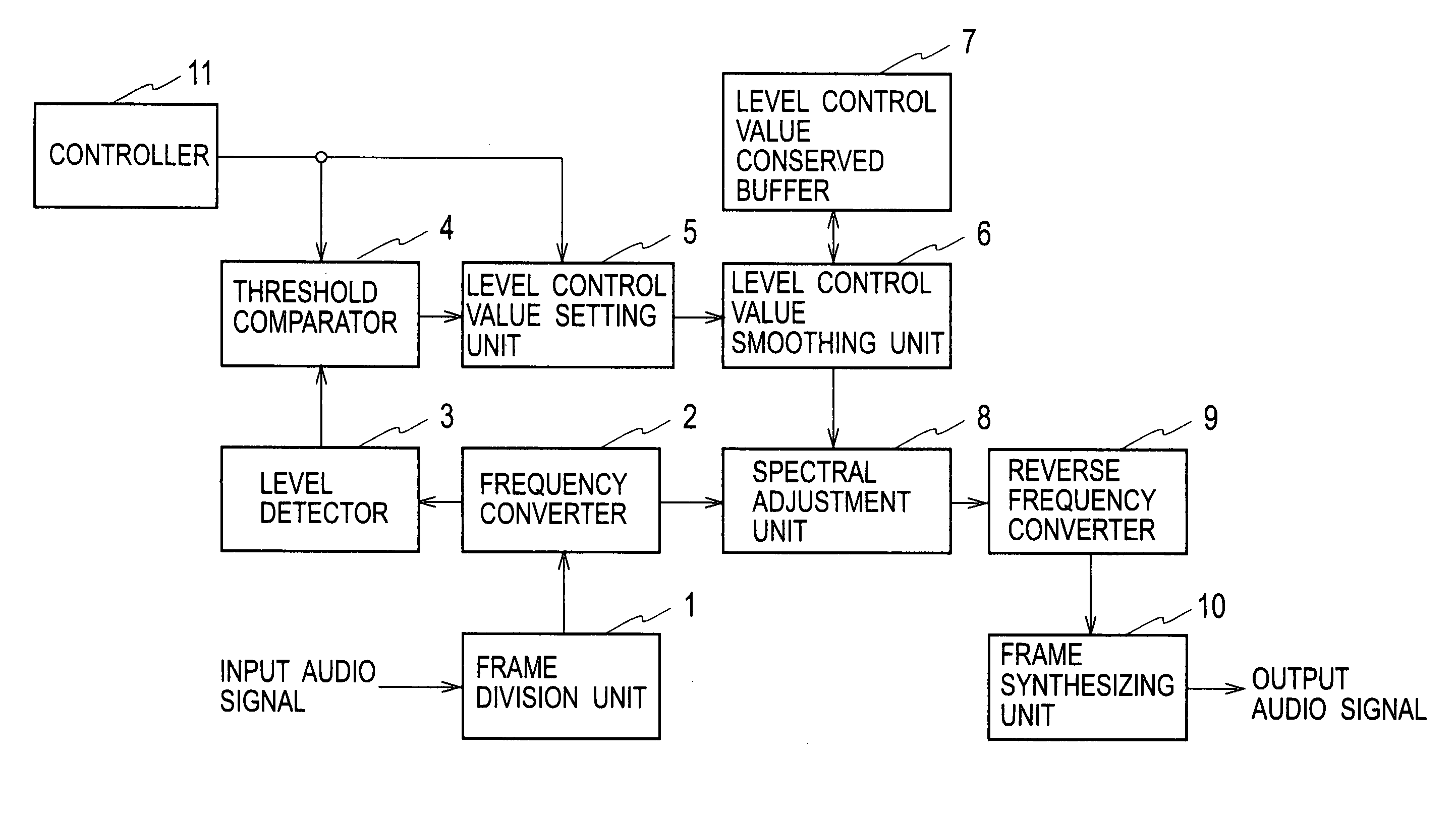
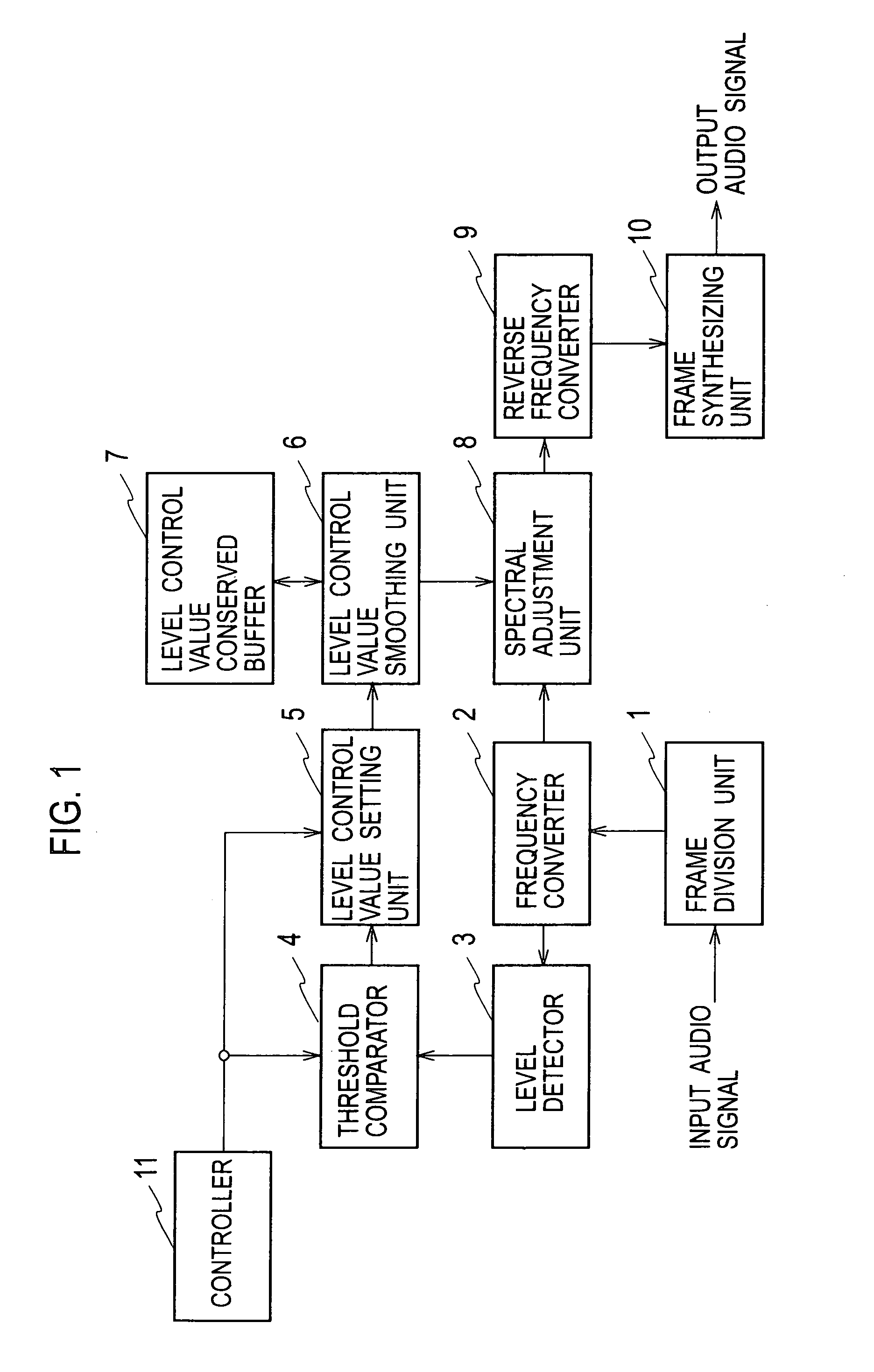
[0038]FIG. 1 is a block diagram showing the constitution of an audio signal processing device related to the embodiment of the present invention. As shown in FIG. 1, the audio signal processing device of the embodiment includes a frame division unit 1, a frequency converter 2, a level detector 3, a threshold comparator 4, a level control value setting unit 5, a level control value smoothing unit 6, a level control value conserved buffer 7, a spectral adjustment unit 8, a reverse frequency converter 9, a frame synthesizing unit 10 and a controller 11.

[0039]The frame division unit 1 divides audio signals in units of frames obtained by compartmentalizing digital signals inputted from an outside every a predetermined number of samples.

[0040]The frequency converter 2 converts the audio signals inputted through the frame division unit 1 from ti...


PUM


Abstract

In frequency signals obtained by converting input audio signals from time-domain signals to frequency-domain signals, a level control value setting unit 5 establishes a level control value for reducing the levels of spectrums at a noise-components level. A level control value smoothing unit 6 carries out a smoothing process of smoothing the level control value established by the level control value setting unit 5 temporally. A spectral adjustment unit 8 multiplies the level control value after the smoothing process by the frequency signals, performing a level control.

Description

[0001]This is a National Phase Application filed under 35 U.S.C. 371 as a national stage of PCT / JP2009 / 055513, filed on Mar. 19, 2009, which claims foreign priority benefit under 35 USC 119 of Japanese Application No. 2008-076605, filed on Mar. 24, 2008, and which claims foreign priority benefit under 35 USC 119 of Japanese Application No. 2008-334908, filed on Dec. 26, 2008, the entire content of each of which is hereby incorporated herein by reference.TECHNICAL FIELD[0002]The present invention relates to an audio signal processing device and an audio signal processing method, both of which enable noise components included in audio signals to be reduced.BACKGROUND OF ART[0003]Hitherto, there are proposed a variety of techniques of reducing noise components included in audio signals in order to make voice and sound easy to be heard. For instance, a method of spectral deduction is known as a technique of analyzing inputted audio signals in real time and further controlling signals in...

Claims


Application Information

Patent Timeline
Patent Type & Authority Patents(United States)
IPC IPC(8): G10L19/14G10L21/02G10L21/003G10L21/0232G10L25/51G10L25/81
CPCG10L21/0208G10L21/0232H03G3/3005H03G3/3089H04R25/356H04R25/505H04R2225/43H04R2460/01
Inventor YAMABE, TAKAAKIKONISHI, MASAYA
Owner JVC KENWOOD CORP
Learn More