
Resin layer formation method and semiconductor device fabrication method

a semiconductor device and layer formation technology, applied in semiconductor devices, semiconductor/solid-state device details, electrical devices, etc., can solve the problems of difficult micronized interconnection, large cost, long time-consuming planarization, etc., to prevent abraded or broken, and reduce the thermal expansion coefficient

Active Publication Date: 2012-11-27
FUJITSU LTD
View PDF19 Cites 4 Cited by
  • Summary
  • Abstract
  • Description
  • Claims
  • Application Information

AI Technical Summary

Benefits of technology

This method effectively planarizes resin layers while preventing cutting tool abrasion, enabling the fabrication of semiconductor devices at reduced costs and improving the precision of interconnections.

Problems solved by technology

It is difficult to micronized interconnections at a small pitch on insulation layer having large steps.
However, the planarization by CMP causes relatively large costs.
When a thickness to be polished is as relatively large as several micrometers, the planarization takes long time.
However, in grinding with a grinding wheel, when the material of an insulation layer is a resin, the resin stays on the surface of the grinding wheel and clogs.
The grinding with a grinding wheel is thus unsuitable to planarize a resin layer.
However, when a resin layer containing a filler (substance) of an inorganic material, such as silica or others, is cut with a cutting tool of diamond or others, the filler contained in the resin layer rapidly abrades or breaks the tip of the cutting tool.
When a resin layer and electrodes are cut with a cutting tool having the tip abraded or broken, fins are formed in the cut electrodes, the resin stays on the surfaces of the electrodes, or the surface of the resin layer and the surfaces of the electrodes are damaged.

Method used


Image

  • Resin layer formation method and semiconductor device fabrication method
  • Resin layer formation method and semiconductor device fabrication method
  • Resin layer formation method and semiconductor device fabrication method

Examples


first embodiment

A First Embodiment

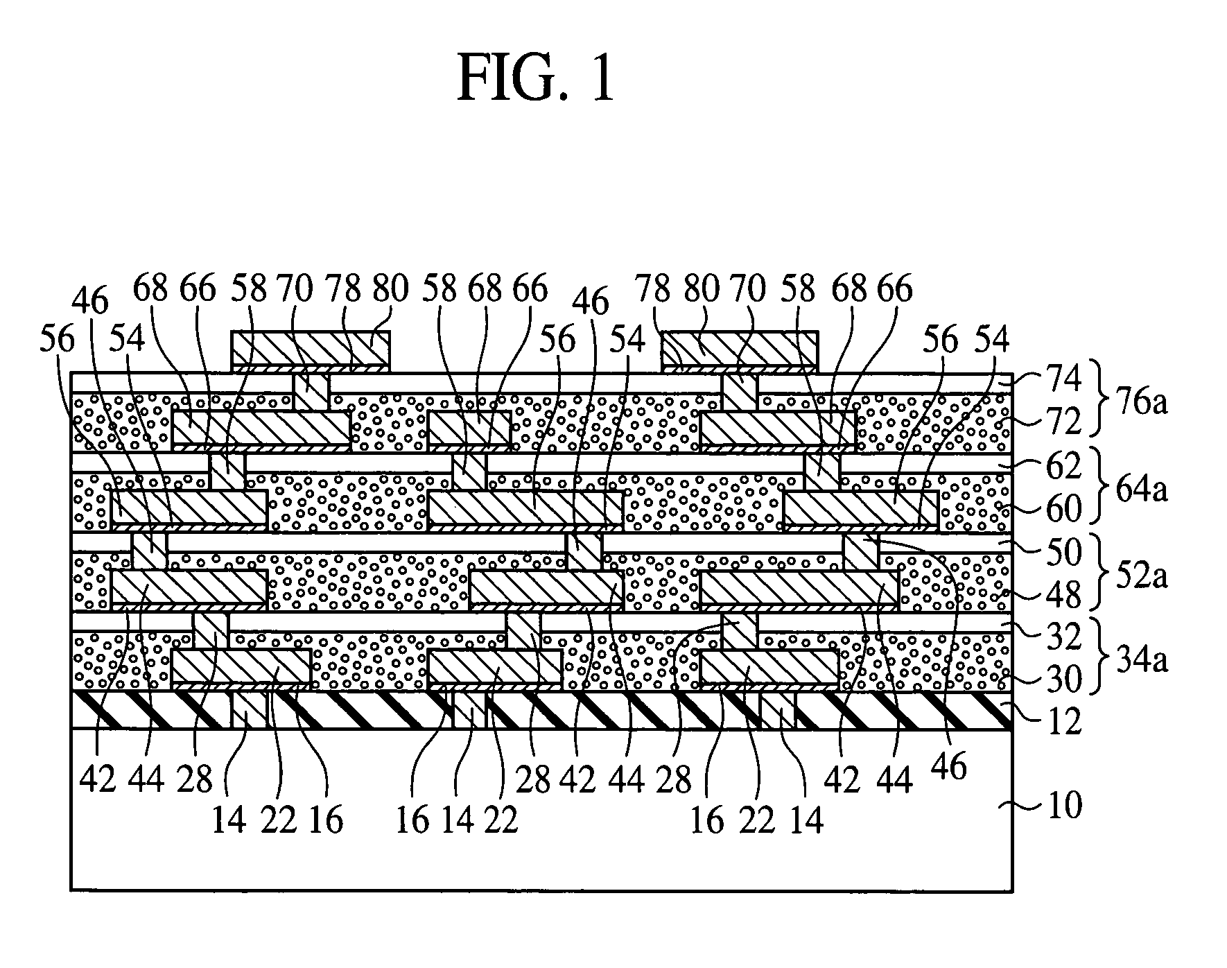
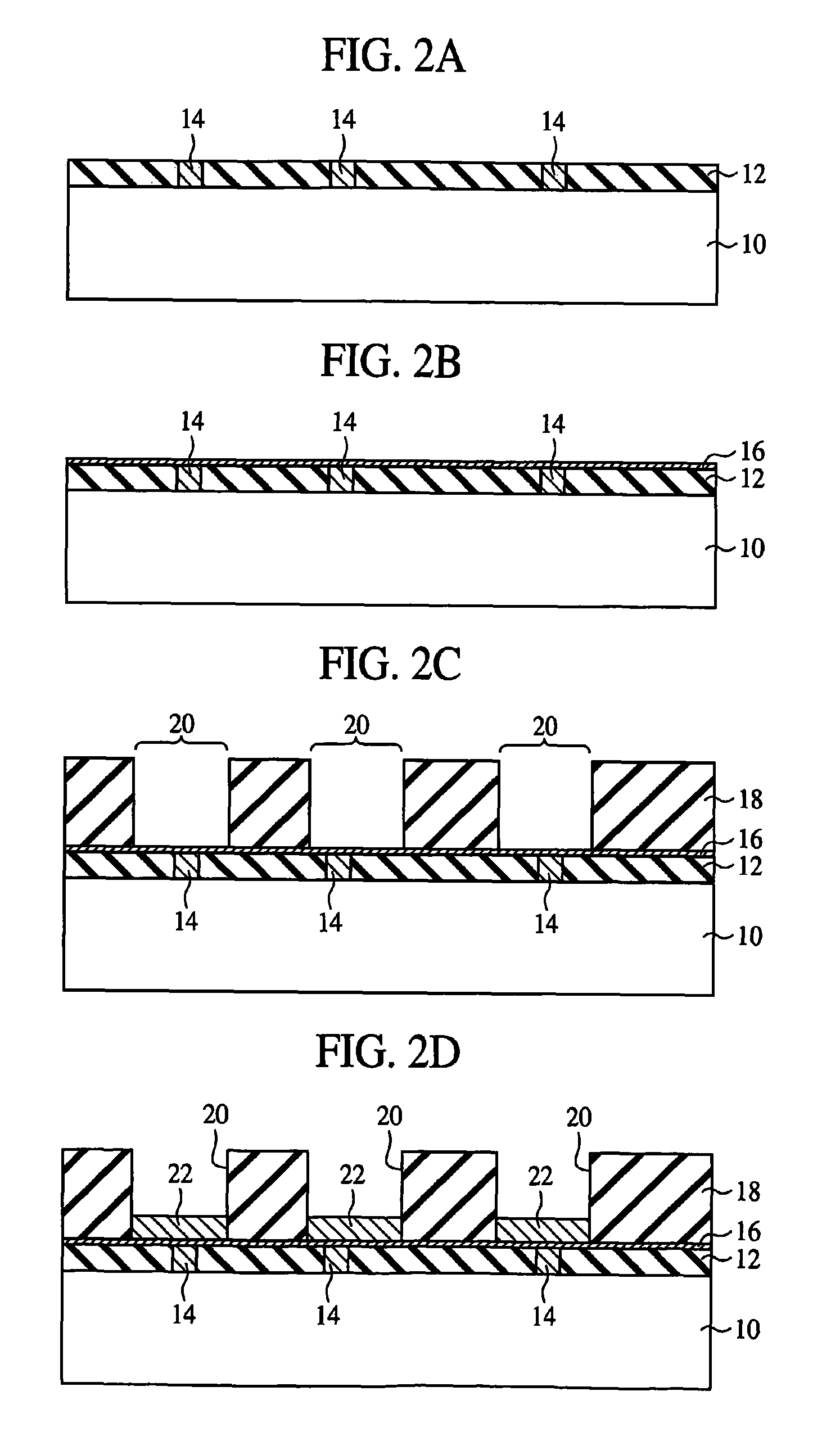
[0064]The resin layer formation method according to a first embodiment of the present invention, the semiconductor device using the resin layer formation method, and the semiconductor device fabrication method will be explained with reference to FIGS. 1 to 14B. FIG. 1 is a sectional view of the semiconductor device according to the present embodiment.

[0065](The Semiconductor Device)

[0066]First, the semiconductor device according to the present embodiment will be explained with reference to FIG. 1.

[0067]The semiconductor substrate 10 is, e.g., a silicon wafer. A logic circuit including active elements (not illustrated), such as transistors, etc. and / or passive elements (not illustrated), such as capacitor elements, etc., and / or a memory circuit, etc. (not illustrated) are formed on the semiconductor substrate 10. On such semiconductor substrate 10, inter-layer insulation films 12 of, e.g., silicon oxide film are formed. The inter-layer insulation films 12 are formed...

second embodiment

A Second Embodiment

[0182]The resin layer formation method according to a second embodiment of the present invention, the semiconductor device using the resin layer formation method and the semiconductor device fabrication method will be explained with reference to FIGS. 15 to 25B. FIG. 15 is a sectional view of the semiconductor device according to the present embodiment. The same members of the present embodiment as those of the resin layer formation method, the semiconductor device and the semiconductor device fabrication method according to the first embodiment illustrated in FIGS. 1 to 14B are represented by the same reference numbers not to repeat or to simplify their explanation.

[0183](The Semiconductor Device)

[0184]The semiconductor device according to the present embodiment is characterized mainly in that first layers 110, 116, 122, 128 of resin layers 114a, 120a, 126a, 132a contain a filler of an inorganic material by a first content ratio, and second layers 112, 118, 124, ...

third embodiment

A Third Embodiment

[0249]The resin layer formation method according to a third embodiment of the present invention, the semiconductor device using the resin layer formation method and the semiconductor device fabrication method will be explained with reference to FIGS. 26 to 35. FIG. 26 is a sectional view of the semiconductor device according to the present embodiment. The same members of the present embodiment as those of the resin layer formation method according to the first or the second embodiment, the semiconductor device using the resin layer formation method and the semiconductor device fabrication method are represented by the same reference numbers not to repeat or to simplify their explanation.

[0250](The Semiconductor Device)

[0251]The semiconductor device according to the present embodiment is characterized mainly in that first layers 82, 88, 94, 100 and second layers 84, 90, 96, 102 forming resin layers 96a, 92a, 98a, 104a are formed by spin coating.

[0252]As illustrated ...


PUM


Abstract

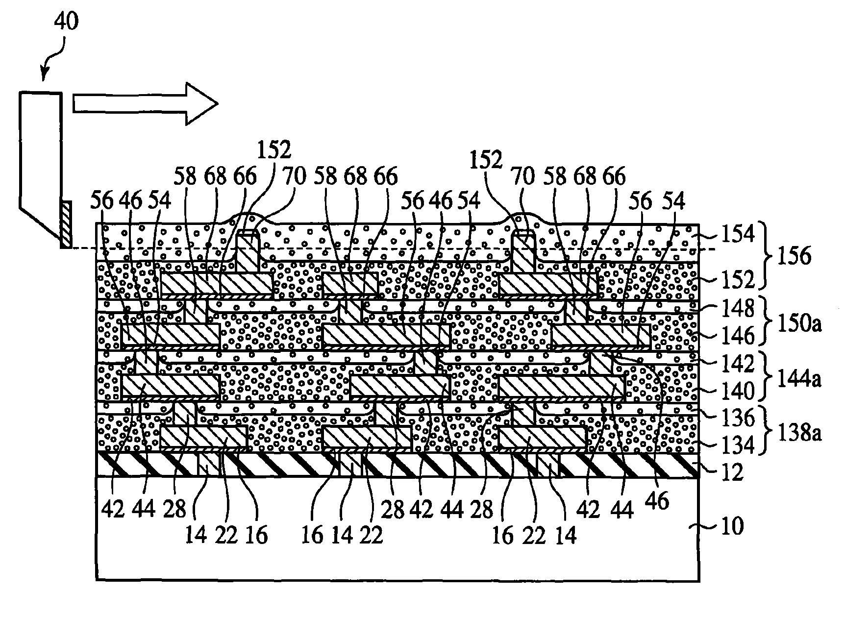
The resin layer formation method comprises the step of forming on a substrate 10 a resin layer 34 for containing a substance for decreasing the thermal expansion coefficient to thereby forming a resin layer 34 having said substance localized in the side thereof nearer to the substrate 10; and the step of cutting the surface of the resin layer 34 with a cutting tool 40 to planarize the surface of the resin layer 34. The resin layer 34 as said substance for decreasing the thermal expansion coefficient localized in the side thereof nearer to the substrate 10, and the surface of the resin layer 34 is cut to planarize the surface of the resin layer 34, whereby the extreme abrasion and breakage of the cutting tool 40 by said substance for decreasing the thermal expansion coefficient can be prevented.

Description

CROSS-REFERENCE TO RELATED APPLICATION[0001]This application is based upon and claims priority of Japanese Patent Application No. 2006-44128, filed on Feb. 21, 2006, the contents being incorporated herein by reference.BACKGROUND OF THE INVENTION[0002]The present invention relates to a resin layer formation method, a semiconductor device and semiconductor device fabrication method.[0003]For the large integration and large density of semiconductor devices, etc., it is advantageous to form multilayer interconnections.[0004]However, when a multilayer interconnection structure is formed by simply laying interconnections and insulation layers (inter-layer insulation films), large steps, i.e., large concavities and convexities are formed in the surfaces of the insulation layers.[0005]It is difficult to micronized interconnections at a small pitch on insulation layer having large steps. Accordingly, it is very important to planarize the surfaces of the insulation layers.[0006]As a technique...

Claims


Application Information

Patent Timeline
Patent Type & Authority Patents(United States)
IPC IPC(8): H01L23/538H01L33/52
CPCH01L21/76801H01L21/76819H01L21/7684H01L21/76885H01L23/53238H01L23/5329H01L2924/0002H01L2924/00
Inventor NAKAGAWA, KANAETANI, MOTOAKI
Owner FUJITSU LTD
Learn More