
Modular lighting system and method

a lighting system and module technology, applied in the field of modules, can solve the problems of lighting fixtures and interconnections sometimes failing or requiring replacement, difficult or impossible to replace lighting fixtures located between two adjacent lighting fixtures or to replace interconnections

Active Publication Date: 2012-11-20
USAI LLC
View PDF4 Cites 65 Cited by
  • Summary
  • Abstract
  • Description
  • Claims
  • Application Information

AI Technical Summary

Benefits of technology

[0010]Accordingly, it is an object of the present invention to provide a modular lighting system having a number of individual, elongated lighting fixtures electrically inter-connectable in an end-to-end fashion where a lighting fixture within a string of lighting fixtures arranged at a minimum spacing distance can be removed and replaced, without damaging or removing any of the other lighting fixtures in the installation regardless of how many lighting fixtures are interconnected and regardless of the total length of the installation.
[0012]It is another object of the present invention to provide a modular lighting system where adjacent lighting fixtures can be electrically interconnected without requiring that the lighting fixtures be spaced apart from one another, to avoid dark spots between adjacent lighting fixtures to provide an even level of illumination.
[0018]In other embodiments, the first and second lighting fixtures are mounted to the support structure with the longitudinal axes thereof in alignment and with one of the ends of the first lighting fixture closely abutting one of the ends of the second lighting fixture, and the first electrical inter-connector is disconnectable from both of the first and second lighting fixtures without disturbing the first or second lighting fixtures.

Problems solved by technology

Illumination needs sometimes change after lighting systems are installed, and, while lighting systems are usually designed to last many years, lighting fixtures and inter-connectors sometime fail or require replacement.
With the prior lighting systems it is difficult or impossible to replace a lighting fixture located between two adjacent lighting fixtures or to replace an inter-connector between lighting fixtures, when the lighting fixtures are mounted at the minimum spacing distance, without removing or damaging the lighting fixtures on either side, or, in some cases, without removing all of the other lighting fixtures.
Therefore, the effort and cost of replacing individual lighting fixtures, or replacing or modifying inter-connectors, in such prior systems is significant and has been a deterrent to their adoption and use.
However, such prior art lighting systems can include dark spots between lighting fixtures because portions of the inter-connectors of the prior systems are located between adjacent lighting fixtures and require that the lighting fixtures be spaced apart from one another at an undesirably large spacing distance to accommodate the presence of the central portion of the inter-connector.

Method used


Image

  • Modular lighting system and method
  • Modular lighting system and method
  • Modular lighting system and method

Examples


Embodiment Construction

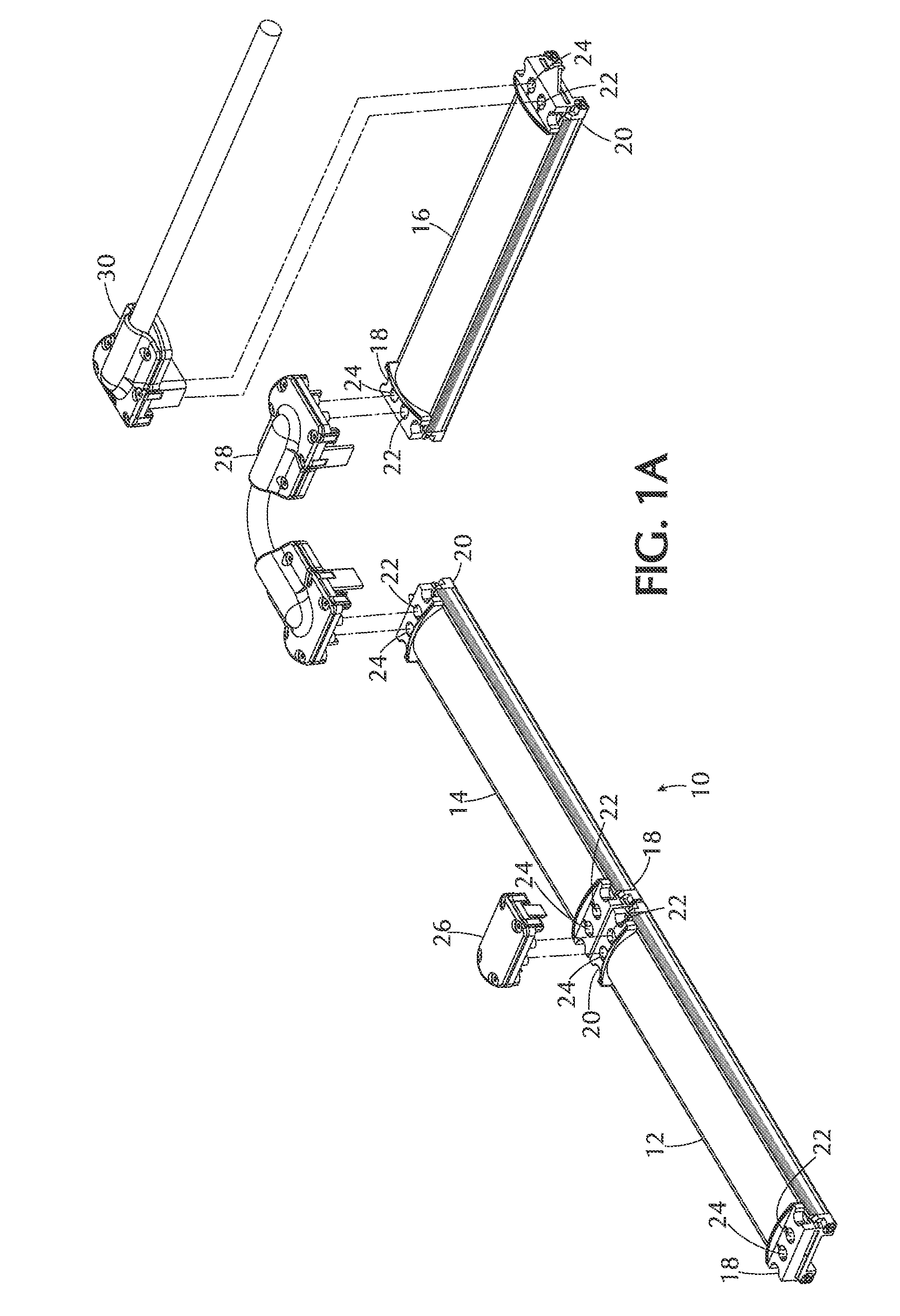
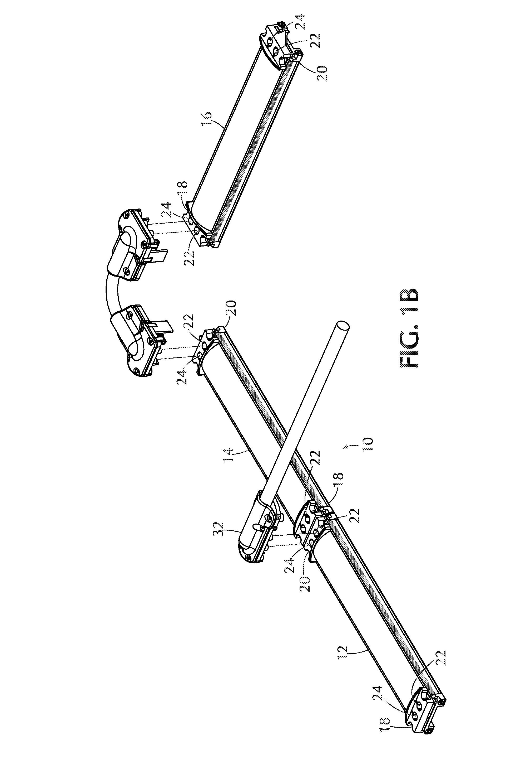
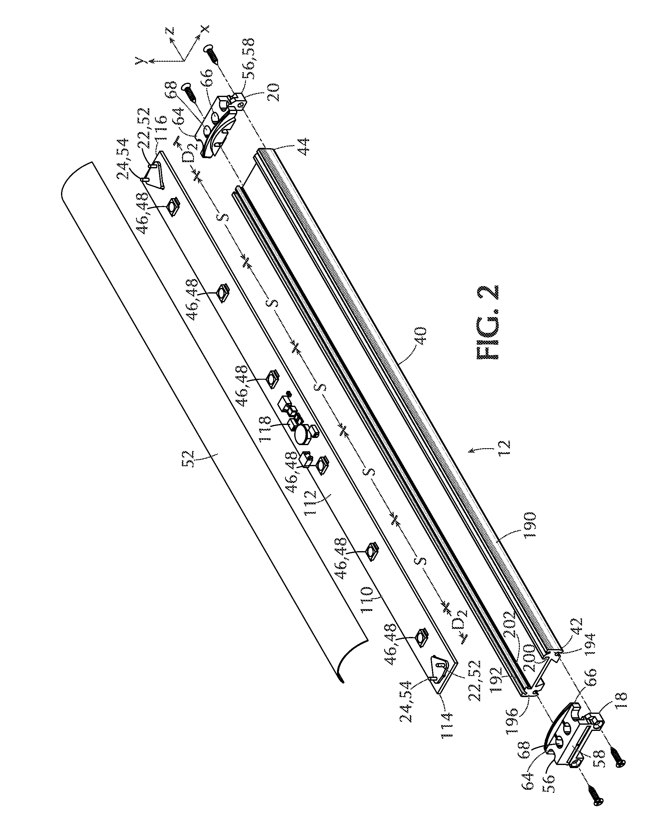
[0040]Referring to FIGS. 1A and 1B, a lighting system 10 constructed according to the invention includes a number of elongated lighting fixtures 12, 14, 16 adapted for electrical interconnection in an end-to-end fashion in a string or “daisy chain.” The lighting fixtures 12, 14, 16 have first and second opposed ends 18, 20 and have electrical connectors 22, 24 adjacent each opposed end 18, 20. The lighting fixtures can be fixed to a support structure (not shown) such as within a display case, shelf, or cove, or another suitable support structure.

[0041]A power source, such as a low-voltage, direct current (DC) power source (not shown), or another suitable type or voltage-level power source, is connected to one of the lighting fixtures (preferably a lighting fixture at one at an end of the string), which passes power to all of the other lighting fixtures. Alternatively, an integrated power supply (not shown) could be enclosed within one of the lighting fixtures (for example an end-mos...


PUM


Abstract

A modular lighting system has first, second and third lighting fixtures adapted for end-to-end electrical interconnection. The lighting fixtures are mounted to a support structure in a closely abutting relationship with the longitudinal axes thereof in alignment. First and second electrical inter-connector are removably connected to the first and second lighting fixtures and the second and third lighting fixtures, respectively. The first and second electrical inter-connectors are connectable and disconnectable from a top of the lighting fixtures without dismounting the lighting fixtures, and the second lighting fixture intermediate the other two lighting fixtures being dismountable from the support structure without dismounting the other two lighting fixture by removing the first and second electrical inter-connectors from the top of the lighting fixtures.

Description

CROSS-REFERENCE TO RELATED APPLICATIONS[0001]The present application claims the benefit under 35 U.S.C. §119(e) of the U.S. Provisional Patent Application Ser. No. 61 / 182,540, filed on May 29, 2009, the content of which is incorporated herein by reference.FIELD OF THE INVENTION[0002]This invention pertains to the field of modular lighting systems, and, in particular, to modular lighting systems having a number of elongated, lighting fixtures adapted for electrical interconnection in an end-to-end fashion.BACKGROUND OF THE INVENTION[0003]It is known to use modular lighting systems to illuminate extended areas, such as within a display case or underneath a shelf or in a cove. Such prior modular lighting systems, which are sometimes referred to as linear lighting systems, typically include a number of elongated lighting fixtures which can be mounted to a surface or support structure, and which are electrically interconnected in an end-to-end fashion in a string or “daisy chain”, often ...

Claims


Application Information

Patent Timeline
Patent Type & Authority Patents(United States)
IPC IPC(8): F21S4/00
CPCF21S2/005F21S4/008F21V21/005F21Y2101/02F21S4/28F21Y2115/10
Inventor MAYER, STANLEYFUCHS, PATRICKWRAY, DONALD L.
Owner USAI LLC
Learn More