Multi-component electronic system having leadframe with support-free with cantilever leads

a multi-component electronic system and cantilever lead technology, applied in the direction of semiconductor devices, semiconductor/solid-state device details, electrical apparatus, etc., can solve the problems of general interference with existing board designs, involvement and failure of metal pads and bumps, and achieve rapid turn-around time and without specific attention to precision

Active Publication Date: 2012-11-06
TEXAS INSTR INC
View PDF9 Cites 0 Cited by
  • Summary
  • Abstract
  • Description
  • Claims
  • Application Information

AI Technical Summary

Benefits of technology

[0006]It is a technical advantage of the invention that the pallet may be made of an inexpensive metal or other inert material, which tolerates the temperatures for assembling the components on the leadframe. It is another technical advantage that the pallet can be manufactured according to any leadframe design, without specific attention to precision and in rapid turn-around time.
that the pallet may be made of an inexpensive metal or other inert material, which tolerates the temperatures for assembling the components on the leadframe. It is another technical advantage that the pallet can be manufactured according to any leadframe design, without specific attention to precision and in rapid turn-around time.

Problems solved by technology

Applicants investigated a large number of electronic molded systems such as power switches, voltage regulators, etc., which had received complaints from customers for exhibiting a high risk of developing electrical shorts during solder attachment to boards, further a tendency of delaminating the molding compound from the metal leadframe with subsequent sensitivity to moisture ingress and even metal corrosion, and a general interference with existing board designs.
Applicants identified as the root cause for the overwhelming majority of complaints the involvement and failure of the metal pads and bumps, which are exposed from the underside of the package not for an electrical function, but as leftovers from their auxiliary function of physically supporting the thin cantilever leads during the assembly step of soldering the components to the half-etched leads.

Method used


Image

  • Multi-component electronic system having leadframe with support-free with cantilever leads
  • Multi-component electronic system having leadframe with support-free with cantilever leads
  • Multi-component electronic system having leadframe with support-free with cantilever leads

Examples


Embodiment Construction

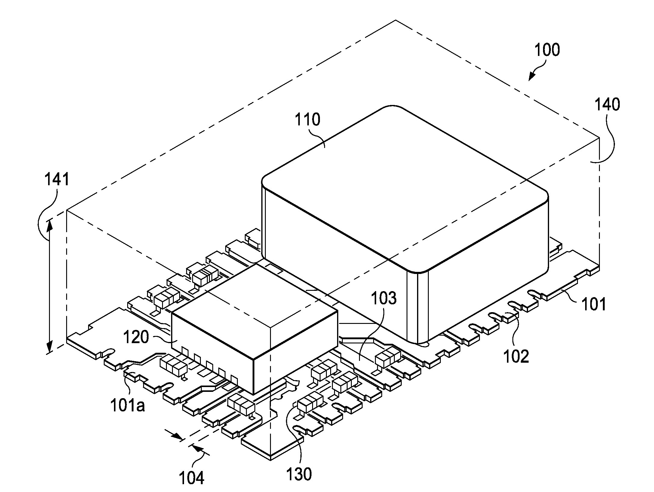
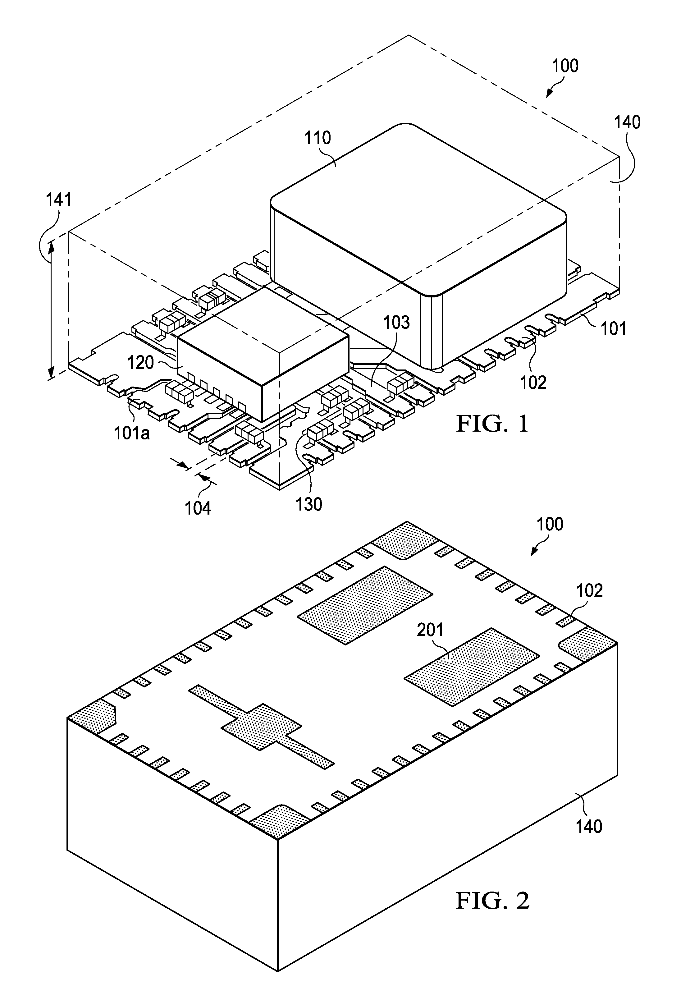
[0013]FIG. 1 displays a top view of an exemplary packaged electronic system generally designated 100. The system is based on a QFN / SON-type metal leadframe 101, preferably made of copper or a copper alloy. The leadframe has, like generally in Quad Flat No-Lead (QFN) and Small Outline No-Lead (SON) devices, no metallic leads shaped as cantilevers protruding from the device package; rather, the metallic contacts for electrical connection and for board attach (by pressure or soldering) are provided by flat metal pads. As FIG. 1 indicates, the lead ends 102, shaped as flat pads, are arrayed along the periphery of leadframe 101. The lead ends 102 belong to metal leads 103, which are elongated and extend from the periphery towards the center region of the leadframe. Adjacent elongated leads 103 are spaced by gaps 104. More details of the structure, organization, and thicknesses of the leads 103 of leadframe 101 are discussed in FIG. 4.

[0014]As FIG. 1 further shows, system 100 includes a p...


PUM


Abstract

A pallet (501) supporting a half-etched leadframe with cantilever-type leads (403) without metallic supports during the step of attaching components (510) to the leads in order to assemble an electronic system. After assembly, the pallet is removed before the molding step that encapsulates (601a) the components on the leadframe and mechanically supports (601b) the cantilever leads. The pallet is machined from metal or inert plastic material, tolerates elevated temperatures during soldering, and is reusable for the next assembly batch.

Description

FIELD OF THE INVENTION[0001]The present invention is related in general to the field of semiconductor devices and processes, and more specifically to structure and fabrication method of a multi-component electronic system having a leadframe with support-free cantilever leads.DESCRIPTION OF RELATED ART[0002]Electronic products in commercial applications of fields such as telecom, home audio, and regulator products often need systems, which can switch power supplies, regulate and stabilize voltages, and work as dc-dc converters. In order to operate properly, these systems not only need to have high efficiency, but should preferably also have small dimensions and very low cost. As an example of a system, popular power switches involve a metal leadframe, on which a plurality of discrete electronic components are assembled and then, as a unit, wrapped into a plastic encapsulation. The components may include a wire-bonded and packaged MOS Field Effect Transistor (FET) with low resistance ...

Claims


Application Information

Patent Timeline
Patent Type & Authority Patents(United States)
IPC IPC(8): H01L23/495
CPCH01L23/495H01L23/4951H01L23/49548H01L23/3107H01L2924/0001H01L2224/16245H01L2224/131H01L2924/1461H01L24/16H01L2924/014H01L2224/13099H01L2924/00H01L2924/14
Inventor AMARO, MICHAEL GKUMMERL, STEVEN AEFLAND, TAYLOR RKODURI, SREENIVASAN K
Owner TEXAS INSTR INC
Why Eureka
Try Eureka