
Certifying device, verifying device, verifying system, computer program and integrated circuit

a verification device and verification system technology, applied in the field of information processing machines, can solve problems such as the loss of reliability of the update module, the hacking of the update module itself, and the inability to force software updates

Inactive Publication Date: 2012-10-23
SOVEREIGN PEAK VENTURES LLC
View PDF64 Cites 24 Cited by
  • Summary
  • Abstract
  • Description
  • Claims
  • Application Information

AI Technical Summary

Benefits of technology

[0012]With the above-described structure, the requesting device, with use of the tamper-resistant generation unit, generates certification information reflecting amounts of characteristics of the computer program. The generated certification information is therefore reliable. Also, the verifying device judges the authenticity of the requesting device using the obtained certification information. This structure therefore produces an excellent advantageous effect that the authenticity can be verified reliably.
[0039]With the above-described structures, the requesting device cannot obtain a key that is dispensable for decrypting the device key unless it deletes the received encryption program. Accordingly, this makes it possible to force the requesting device to delete the encryption program.

Problems solved by technology

However, it is difficult with these technologies to ensure an update of the program when the terminal has already been hacked because in that case, there is a possibility that the reliability of the update module has been lost.
For example, when the update module is also a software program, there is a possibility that the update module itself has been hacked.
When this occurs, a forced software update becomes impossible.
However, the program update system is often created to be large in scale since in many cases it is equipped with a function to perform communication with the Internet or the like.
Therefore, it is practically difficult to generate a program update system that is made of hardware as a whole.

Method used


Image

  • Certifying device, verifying device, verifying system, computer program and integrated circuit
  • Certifying device, verifying device, verifying system, computer program and integrated circuit
  • Certifying device, verifying device, verifying system, computer program and integrated circuit

Examples


embodiment 1

1.7 Modifications of Embodiment 1

[1083](1) Obtaining Update Program

[1084]In the above-described Embodiment 1, when the attestation results in a failure, the CA server device 3002 transmits an operation prohibition notification, and upon receiving this notification, the terminal device 3001 stops the operation and is powered off. However, not limited to this, the terminal device 3001 may be booted, with part of its functions being restricted.

[1085]Alternatively, as is the case with the above-described embodiment and modifications, the CA server device 3002 may transmit an update program for updating each program to a newest version, and the terminal device 3001 may update each program to a newest version by using the received update program.

[1086]After the update, the terminal device 3001 is rebooted and performs the attestation again.

[1087](2) Timing of Attestation

[1088]In the above-described Embodiment 1, when the OS has been loaded into a memory and can be executed, a boot notific...

embodiment 2

2.6 Modifications of Embodiment 2

[1211](1) Specifying Predetermined PCR Value

[1212]As is the case with Modification (3) of Embodiment 1, in the attestation process of the present embodiment, the machine on the verification side may transmit, together with the nonce, identification information indicating one or more PCR values. The machine on the requesting side may read out only the PCR values indicated by the identification information, generate signature data, and transmit the generated signature data. In line with this, the machine on the certification side may extract only log information that corresponds to the PCR values indicated by the received identification information, and transmit the extracted log information.

[1213](2) Plurality of Memory Cards

[1214]The present embodiment has been described using an example where one piece of memory card #2 can be attached to a plurality of terminal devices. However, there may be a converse case where a plurality of memory cards can be ...

embodiment 3

3.5 Modifications of Embodiment 3

[1304](1) Verification between TPMs

[1305]In the embodiment described above, the TPM #1 verifies the authenticity of the TPM #1 after the authenticity of the programs managed by the TPM #1 is proved. However, this is not an indispensable structure.

[1306]After the authenticity of the programs managed by the TPM #1 is proved, the TPM #1 merely activate the TPM #2 and output the PCR value of the OS.

[1307]Conversely, a mutual authentication may be performed between TPMs before the attestation between the memory card 3302 and the TPM #1 is performed.

[1308]In Embodiment 3 above, the method for verifying whether or not the TPM #2 is authentic is not explained in detail. However, an arbitrary method can be employed for this. For example, it may be a method such as the challenge and response which includes a predetermined calculation, or a simple method of checking the TPM identifier.

[1309]In Embodiment 3 above, when the TPM #1 fails to verify the authenticity...


PUM


Abstract

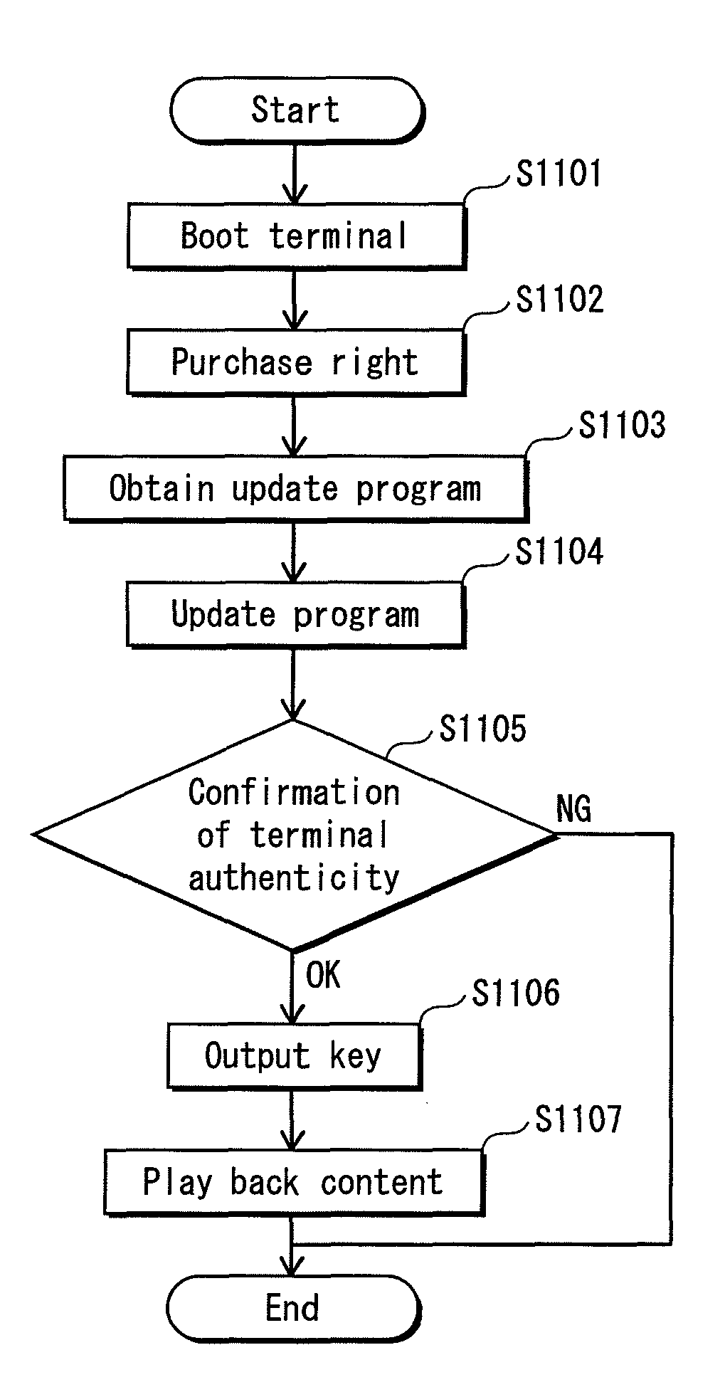
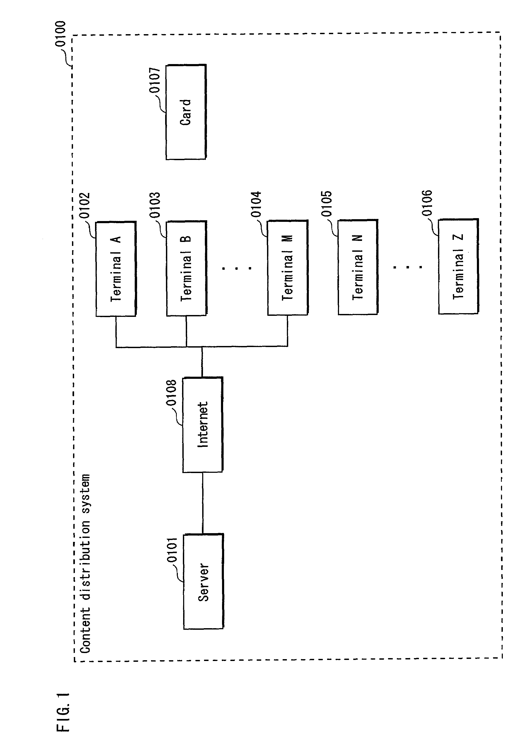
An authentication system verifies an authentic computer program, certifies the authenticity itself, and verifies a certification. The authentication system includes a terminal (e.g., requesting device) and a card (e.g., verifying device). The card stores secret information to be used by the terminal, and an update program for the terminal. The card verifies authenticity of the terminal using information obtained from the terminal. When it judges that the terminal is authentic, the card outputs the secret information to the terminal. When it judges that the terminal is not authentic, the card outputs the update program. The terminal is forced to update the program when it attempts to use the secret information.

Description

BACKGROUND OF THE INVENTIONTECHNICAL FIELD[0001]The present invention relates to a technology, in an information processing machine that operates in accordance with a computer program, of requesting verification of the authenticity of the machine itself and verifying the authenticity of another machine.BACKGROUND ART[0002]As digital contents have become popular, unauthorized copying of contents has become a social issue. When a content processing function is achieved by a software program, the program needs to be protected from unauthorized copying which is attempted by malicious users. When a program achieving a content processing function is tampered or bugged by a malicious user, it is possible that the content in a plain text state may be extracted, or a key used to encrypt the content may be obtained from the program in an unauthorized manner and the content may be decrypted. Digital contents can be redistributed easily via the Internet. Accordingly, if a content in a plain tex...

Claims


Application Information

Patent Timeline
Patent Type & Authority Patents(United States)
IPC IPC(8): H04L29/06G06F21/10G06F21/12G06F21/14G06F21/34G06F21/51G06F21/57G06F21/60G06F21/62G06F21/64
CPCG06F21/10G06F21/445G06F21/57G06F2221/2129G06F21/51H04L9/3234G06F21/575H04L9/0822H04L9/0866
Inventor KANEMURA, KOUICHIITO, YOSHIKATSUHAGA, TOMOYUKIMATSUSHIMA, HIDEKIITO, TAKAYUKI
Owner SOVEREIGN PEAK VENTURES LLC
Learn More