Hydraulic control apparatus of automatic transmission
a technology of hydraulic control apparatus and automatic transmission, which is applied in mechanical devices, transportation and packaging, and gear change shocks. it can solve the problems of leaking the danger of time-consuming gear change shock, and the supply of oil into the discharge oil passage of the b2 brake, so as to reduce the number of switching valves, reduce the number of frictional engagement shocks, and smooth the effect of a second frictional engagement element transition
- Summary
- Abstract
- Description
- Claims
- Application Information
AI Technical Summary
Benefits of technology
Problems solved by technology
Method used
Image
Examples
first embodiment
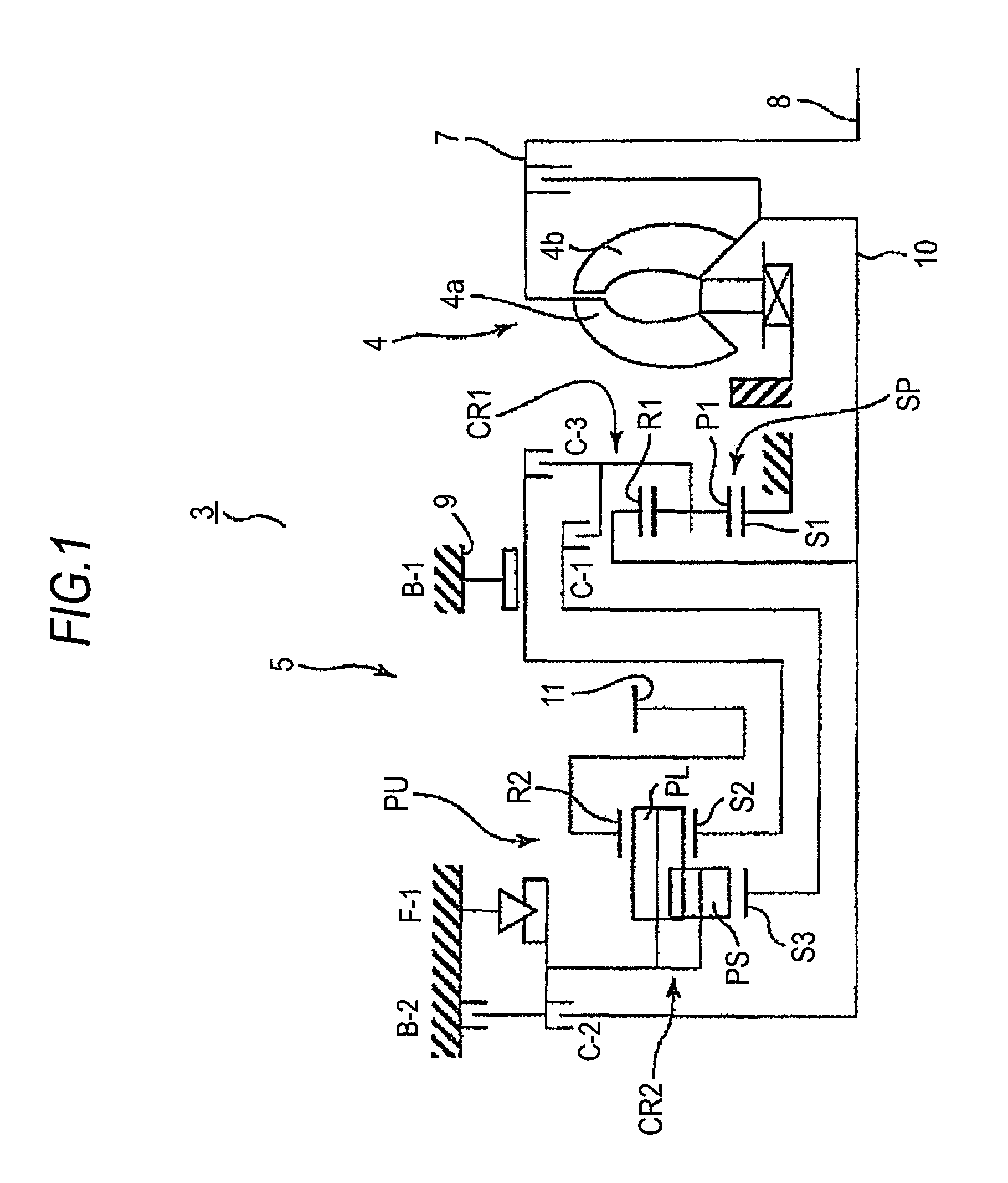
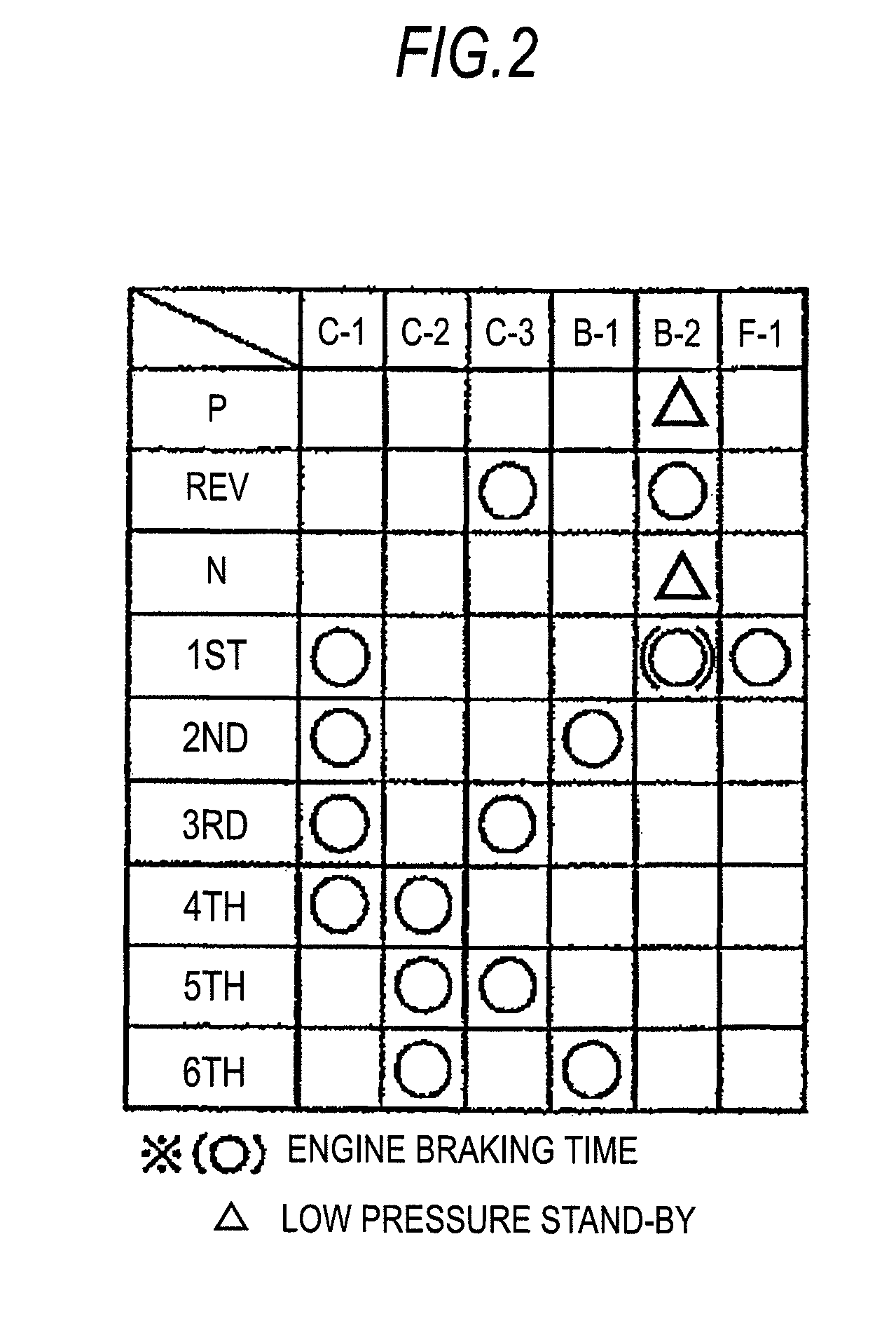
[0019]Hereafter, a description will be given, following FIGS. 1 to 6, of a first embodiment according to the invention.
[0020]Outline Configuration of Automatic Transmission
[0021]Firstly, a description will be given, following FIG. 1, of an outline configuration of an automatic transmission 3 to which the invention can be applied. As shown in FIG. 1, the automatic transmission 3 suitable for use in, for example, an FF type (front engine, front drive) vehicle, having an input shaft 8 of the automatic transmission 3 which can be connected to an engine (not shown), includes a torque converter 4 and an automatic transmission mechanism 5 centered on an axial direction of the input shaft 8.
[0022]The torque converter 4 has a pump impeller 4a connected to the input shaft 8 of the automatic transmission 3 and a turbine runner 4b to which a rotation of the pump impeller 4a is transmitted via a hydraulic fluid, and the turbine runner 4b is connected to an input shaft 10 of the automatic transmi...
second embodiment
[0069]A description will be given, following FIG. 7, of a second embodiment according to the invention.
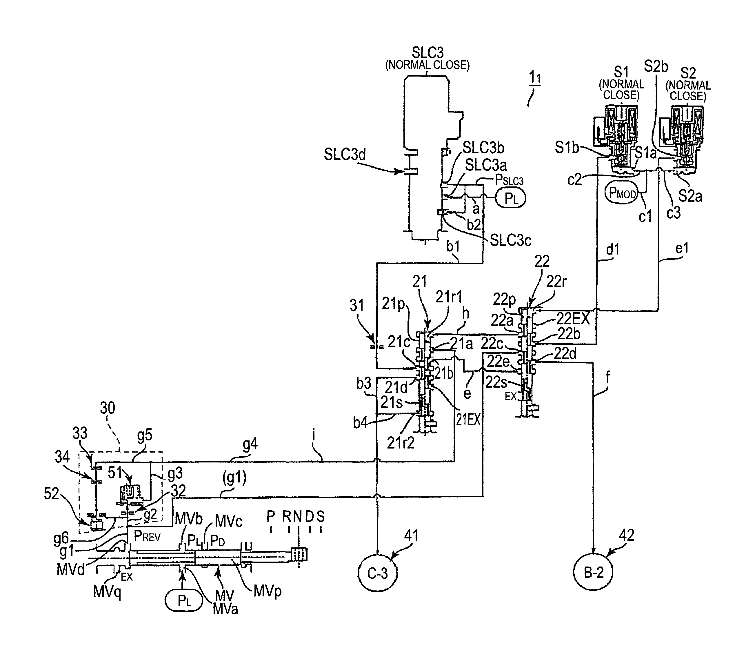
[0070]A hydraulic control apparatus 12 of an automatic transmission 3 of the embodiment is configured including a manual shift valve 61, a hydraulic servo 75 of a clutch C-3 and a hydraulic servo 76 of a brake B-2 as first frictional engagement elements, a linear solenoid valve 62, a first switching portion 63, a second switching portion 66, a third switching portion 70, a reverse range pressure oil passage (an oil passage) k6, a discharge delay oil passage (an oil passage) k7, and an orifice 77 as a delay portion.
[0071]The first switching portion 63 has a first switching valve 65 and a first solenoid valve 64 which switches it depending on whether or not there is a signal pressure output, the second switching portion 66 has a second switching valve 68 and a second solenoid valve 67 which switches it depending on whether or not there is a signal pressure output, and the third switc...
PUM
 Abstract
Description
Claims
Application Information
 - R&D
- Intellectual Property
- Life Sciences
- Materials
- Tech Scout
- Unparalleled Data Quality
- Higher Quality Content
- 60% Fewer Hallucinations
Browse by: Latest US Patents, China's latest patents, Technical Efficacy Thesaurus, Application Domain, Technology Topic, Popular Technical Reports.
© 2025 PatSnap. All rights reserved.Legal|Privacy policy|Modern Slavery Act Transparency Statement|Sitemap|About US| Contact US: help@patsnap.com


