
Hydraulic control device for automatic transmission

a technology of automatic transmission and control device, which is applied in the direction of process and machine control, instruments, etc., can solve the problems of increasing the manufacturing cost of the vehicle, increasing the setup accuracy of original oil pressure and output oil pressure to oil temperature, and the inability to improve the resistance (toughness) against a change in the state of the automatic transmission. , to achieve the effect of improving the variation of the clutch engagement tim

Active Publication Date: 2012-11-06
HONDA MOTOR CO LTD
View PDF8 Cites 0 Cited by
  • Summary
  • Abstract
  • Description
  • Claims
  • Application Information

AI Technical Summary

Benefits of technology

This solution enhances clutch engaging time consistency and reduces shock resistance, enabling single in-gear control of low gear by monitoring torque converter slip ratio to adjust oil pressure commands, thus improving vehicle performance and reducing manufacturing complexity.

Problems solved by technology

Therefore, there has been a problem that it is complicated to carry out such steps for the linear solenoid valve used in the regulating section of the hydraulic control device for the automatic transmission, and this causes manufacturing costs of the vehicle to be increased.
Further, by carrying out control of regulation in the hydraulic control device for the automatic transmission using the above characteristic values, it is possible to heighten setup accuracy of original oil pressure and output oil pressure to oil temperature, but there has been a problem that it is impossible to improve resistance (toughness) against a change in a state of the automatic transmission such as deteriorated state (aged deterioration) due to abrasion of a clutch disk.
However, there has been a problem that in the squat in-gear control, since it is necessary to operate two clutches, not only there is a possibility to be affected by the variation in the oil pressure characteristic to current, but also a usable temperature range for the squat in-gear control is limited.

Method used


Image

  • Hydraulic control device for automatic transmission
  • Hydraulic control device for automatic transmission
  • Hydraulic control device for automatic transmission

Examples


Embodiment Construction

[0035]Hereinafter, a preferred embodiment of a hydraulic control device for an automatic transmission according to the present invention will be described in detail with reference to the appending drawings.

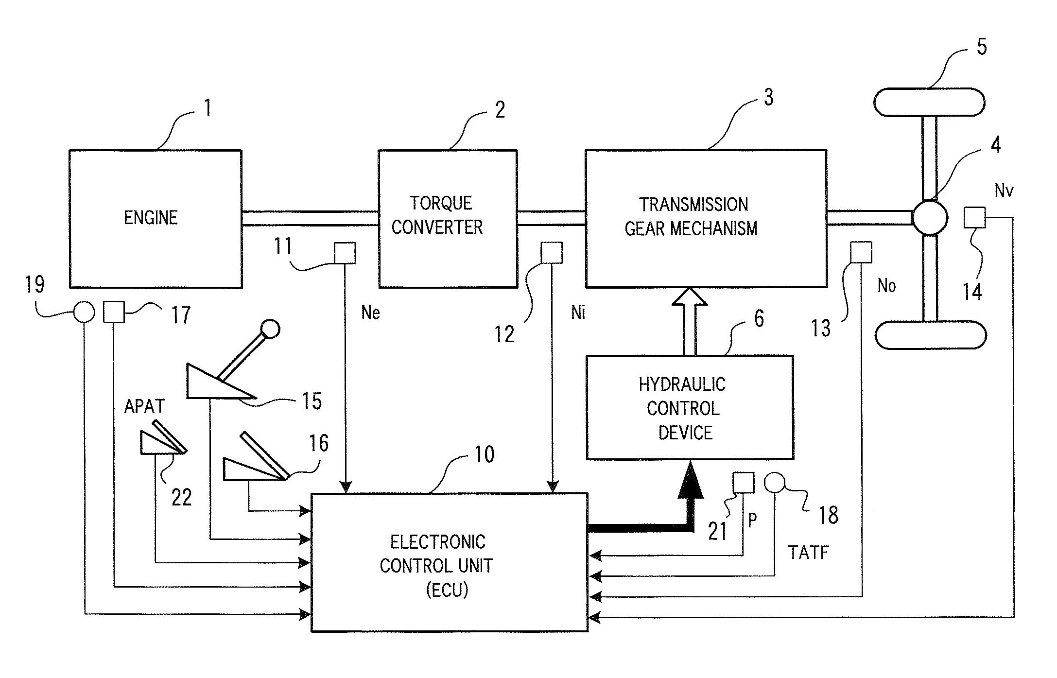
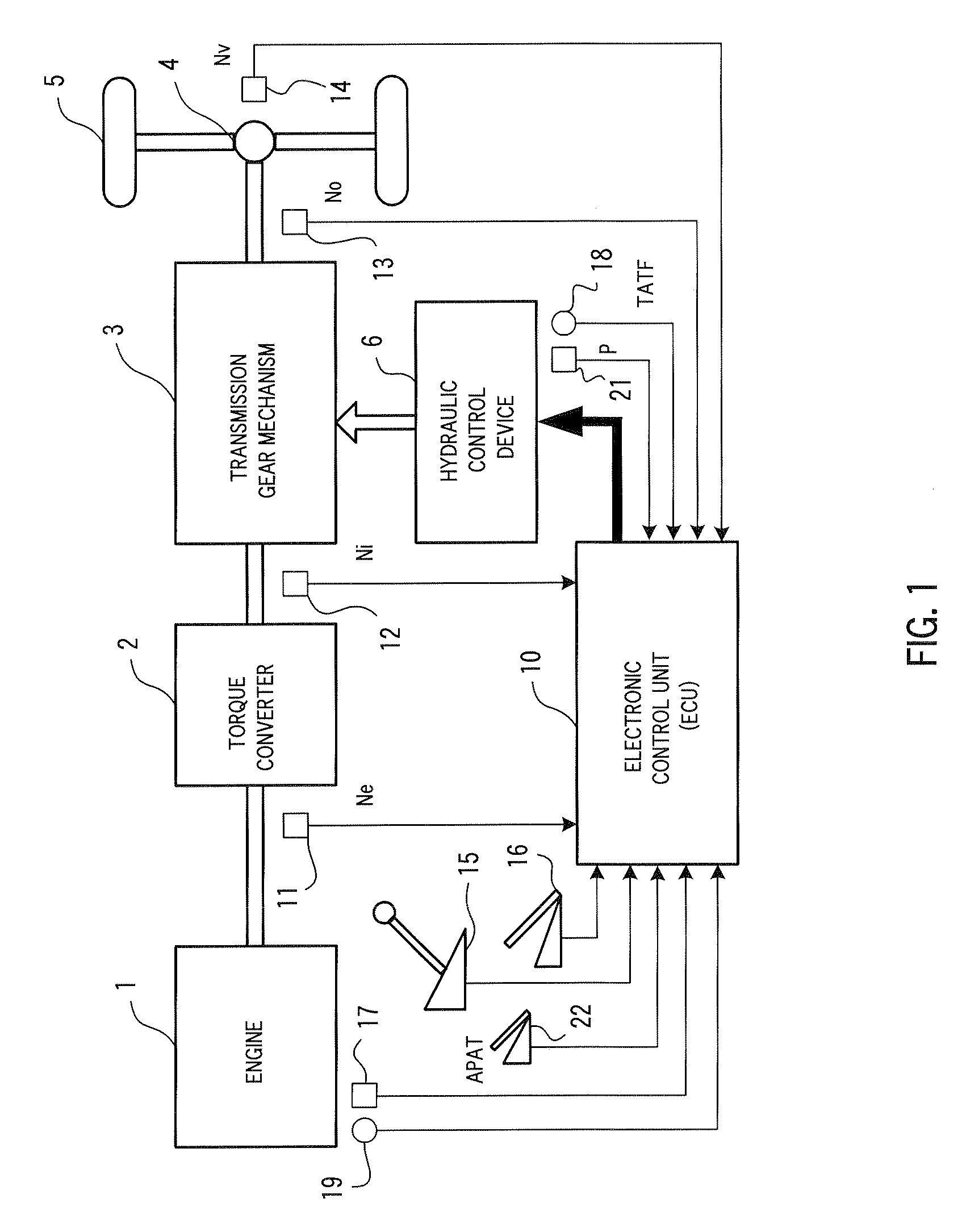
[0036]FIG. 1 is a block diagram schematically showing a power transmission system and a control system for a vehicle provided with a hydraulic control device for an automatic transmission according to one embodiment of the present invention. The power transmission system for the vehicle includes: an engine 1 that is a power source; a torque converter 2 that is a fluid coupling for transmitting rotation output of the engine 1 to a transmission gear mechanism 3; the transmission gear mechanism 3 that changes gears with a set speed ratio when rotation output of the torque converter 2 is inputted thereto; and a differential gear mechanism 4 that distributes (or divides) rotation output of the transmission gear mechanism 3 between right and left wheels (for example, rear wheels) 5. A h...


PUM


Abstract

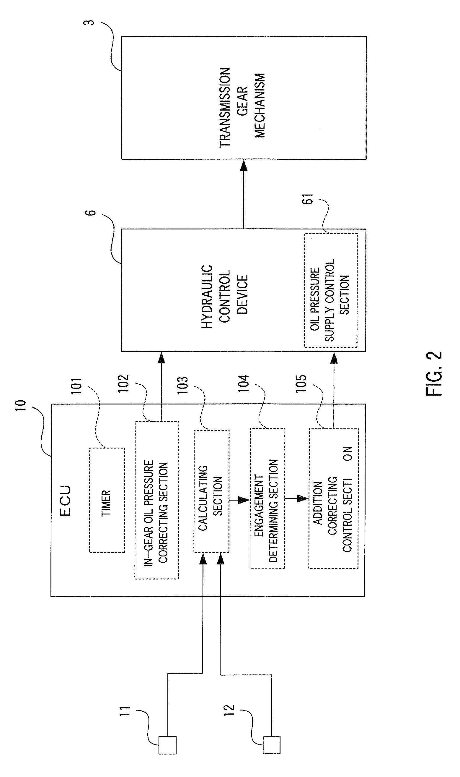
An in-gear oil pressure correcting section corrects engagement control oil pressure set up by an oil pressure supply control section over the entire range to be reduced by first predetermined pressure. An engagement determining section determines, on the basis of a torque converter slip ratio calculated by a calculating section, whether a frictional engagement element of a destination gear starts to engage or not. An addition correcting control section corrects the corrected engagement control oil pressure to add second predetermined pressure thereto in the case where engagement of the frictional engagement element has not been started yet when a timer measures first predetermined time. The addition correcting control section further corrects the corrected engagement control oil pressure to add third predetermined pressure thereto in the case where the engagement of the frictional engagement element has not been started yet when the timer measures second predetermined time.

Description

CROSS-REFERENCE TO RELATED APPLICATION[0001]The present disclosure relates to subject matter contained in Japanese Patent Application No. 2008-124087, filed on May 9, 2008, the disclosure of which is expressly incorporated herein by reference in its entirety.BACKGROUND OF THE INVENTION[0002]1. Field of the Invention[0003]The present invention relates to a hydraulic control device for an automatic transmission of a vehicle, and particularly, the present invention relates to a hydraulic control device for an automatic transmission that corrects engagement control oil pressure at in-gear control if necessary.[0004]2. Description of the Related Art[0005]Heretofore, a setup of engagement control oil pressure for a clutch at in-gear control is carried out so as to meet certain standards for features (setup conditions) of a hydraulic control device for an automatic transmission. The setup conditions include: variation in an oil pressure characteristic to current of a linear solenoid valve ...

Claims


Application Information

Patent Timeline
Patent Type & Authority Patents(United States)
IPC IPC(8): G06F19/00F16H59/42F16H59/46F16H59/68F16H61/04F16H61/68F16H61/684
CPCF16H61/08F16H61/061F16H2059/467
Inventor MAYUMI, SHINSAKUKITANO, KAZUHIKONEMOTO, YOSHIKAZU
Owner HONDA MOTOR CO LTD
Learn More