Hydraulic control device for hybrid drive device
a hybrid drive and control device technology, applied in mechanical equipment, propulsion parts, transportation and packaging, etc., can solve the problems of inability to increase the damper capacity, the driver's discomfort, and the engine clutch is not engaged, so as to relieve the rise in the engagement pressure, suppress the occurrence of engagement shock, and increase the hydraulic passage effect of the discharge resistan
- Summary
- Abstract
- Description
- Claims
- Application Information
AI Technical Summary
Benefits of technology
Problems solved by technology
Method used
Image
Examples
first embodiment
[Schematic Configuration of Hybrid Drive Device]
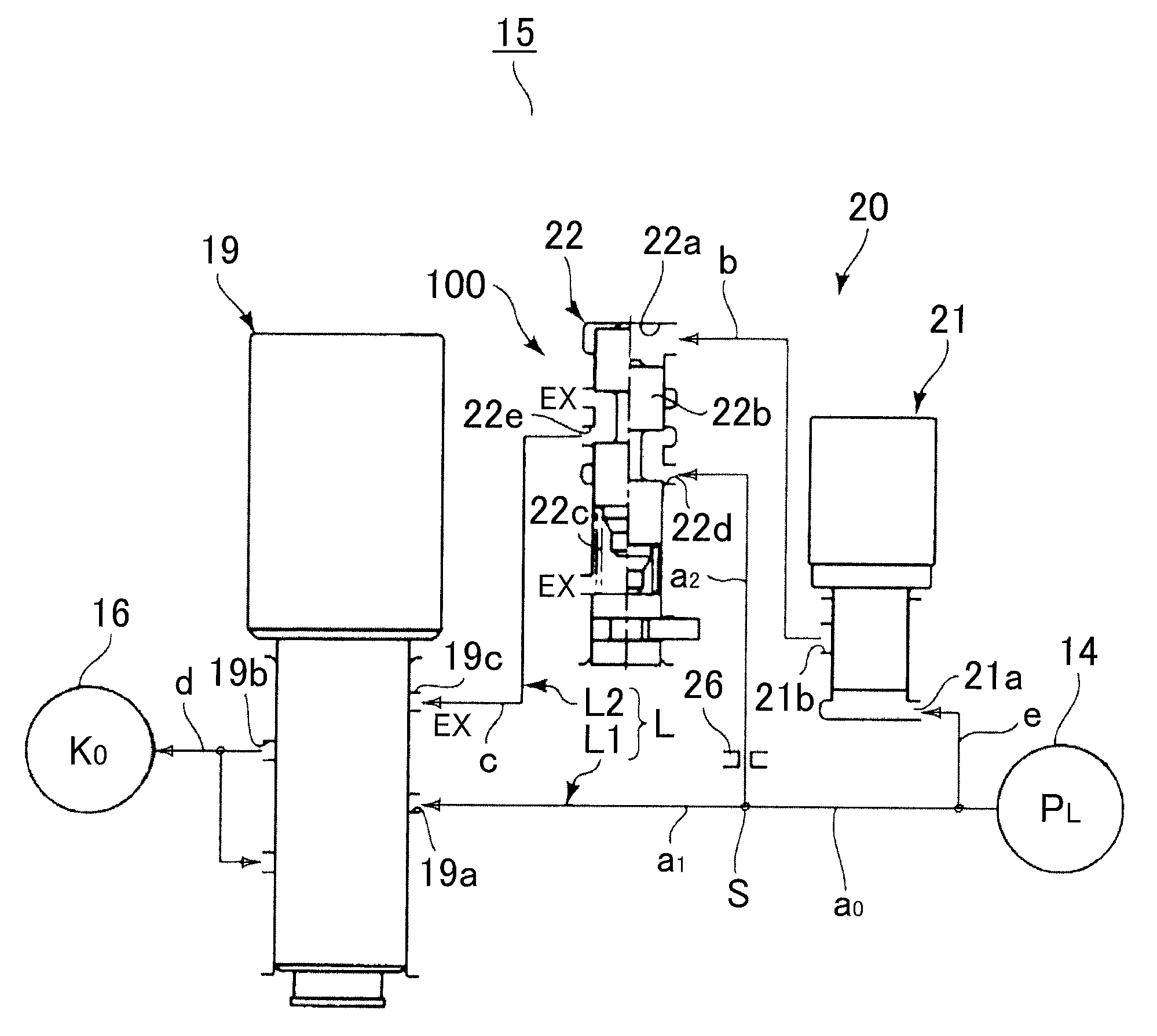
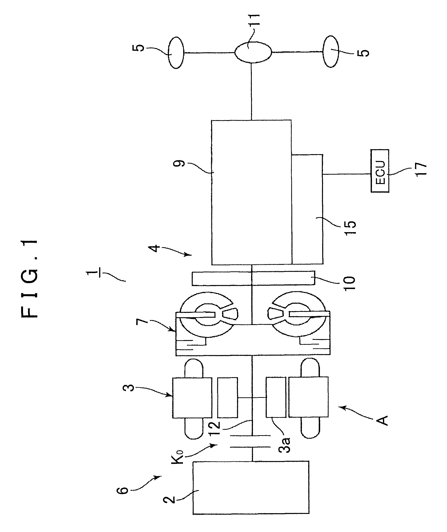
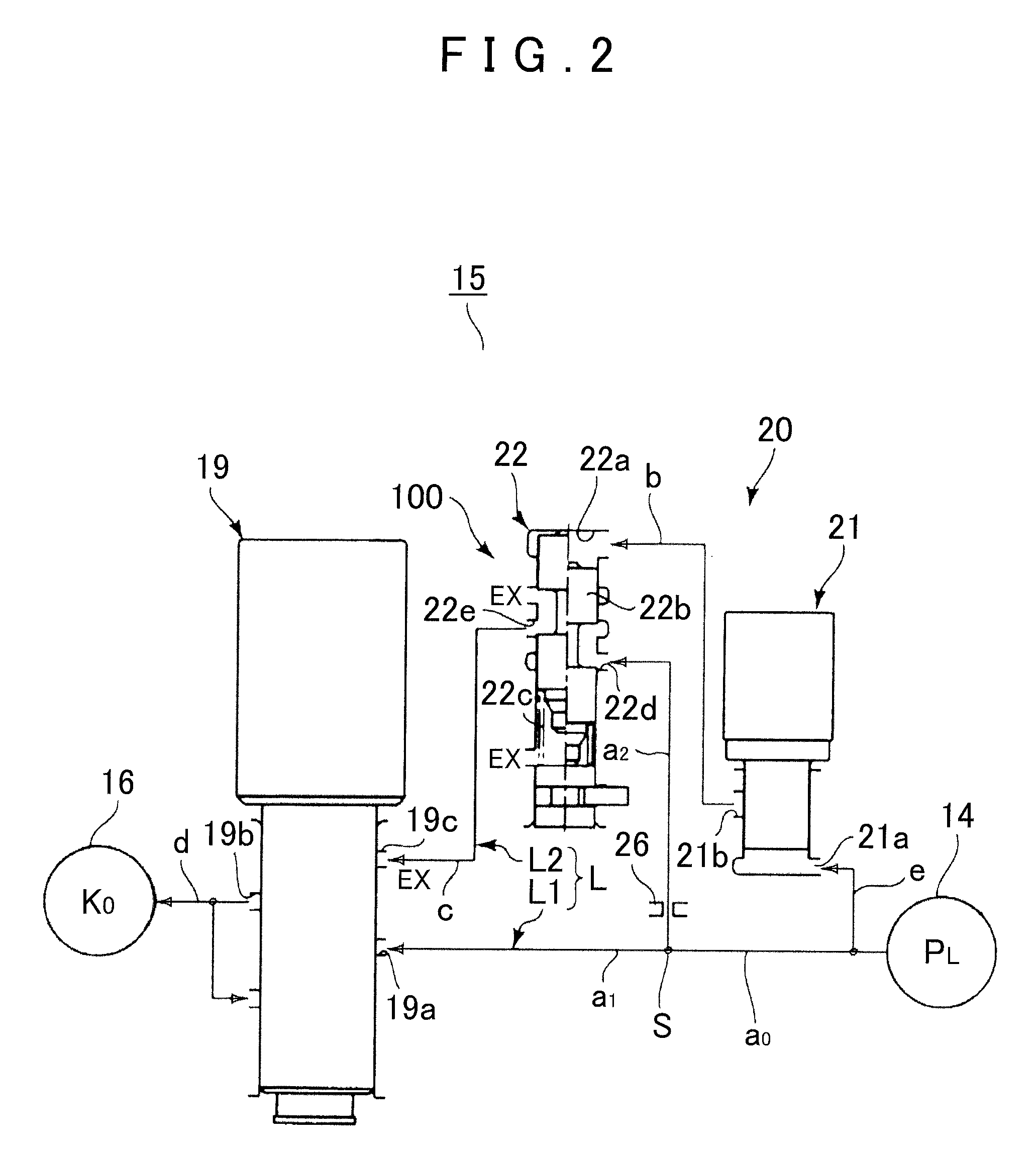
[0023]As shown in FIG. 1, a one-motor hybrid drive device 1 of a front-engine rear-drive (FR) type includes an engine (for example, gasoline engine) 2 disposed with its crankshaft oriented in the front-rear direction of a vehicle when the engine 2 is mounted on the vehicle, and also includes a motor 3, an automatic transmission 4, and drive wheels 5 (in the embodiment, rear wheels) disposed sequentially in this order from an engine side of the hybrid drive device 1 in the axial direction of the engine 2.
[0024]Specifically, in the hybrid drive device 1, the engine 2 and the motor 3, which is provided on a drive wheel side with respect to the engine 2, form a drive section 6. The automatic transmission 4 includes a torque converter 7 and an automatic speed change mechanism 9 formed from a plurality of planetary gear sets. A mechanical oil pump 10 is interposed between the torque converter 7 and the automatic speed change mechanism 9. An ...
second embodiment
[0055]Next, a second embodiment of the present invention will be described. The second embodiment is different from the first embodiment in that a relay valve 40 is disposed downstream of the control solenoid valve 19. Components having the same configuration as those of the first embodiment are not described, and components having the same effect and configuration are given the same reference numerals and names as those of the first embodiment.
[0056]As shown in FIG. 3, the control solenoid valve 19, which controls whether or not the engagement pressure PE is output to the hydraulic servo 16 for the drive section clutch K0, is of a normally closed type as in the first embodiment, and includes the input port 19a, the output port 19b, and the drain port 19c.
[0057]In addition, the relay valve (switching valve) 40 is provided on a hydraulic passage between the control solenoid valve 19 and the hydraulic servo 16 for the clutch K0. The relay valve 40 includes a spool 40b, a spring 40c t...
third embodiment
[0063]Next, a third embodiment of the present invention will be described. The third embodiment is different from the first embodiment in that a control solenoid valve 30 is formed from a normally open valve that outputs the engagement pressure PE to the hydraulic servo 16 for the drive section clutch K0 when de-energized. Components having the same configuration as those of the first embodiment are not described, and components having the same effect and configuration are given the same reference numerals and names as those of the first embodiment.
[0064]As shown in FIG. 4, the control solenoid valve 30, which controls whether or not the engagement pressure PE is output to the hydraulic servo 16 for the drive section clutch K0, is formed from a normally open linear solenoid valve in which an input port 30a and an output port 30b are communicated with each other when de-energized.
[0065]In addition, the relay valve 40 is provided on a hydraulic passage between the source pressure gene...
PUM
 Abstract
Description
Claims
Application Information
 - R&D
- Intellectual Property
- Life Sciences
- Materials
- Tech Scout
- Unparalleled Data Quality
- Higher Quality Content
- 60% Fewer Hallucinations
Browse by: Latest US Patents, China's latest patents, Technical Efficacy Thesaurus, Application Domain, Technology Topic, Popular Technical Reports.
© 2025 PatSnap. All rights reserved.Legal|Privacy policy|Modern Slavery Act Transparency Statement|Sitemap|About US| Contact US: help@patsnap.com


