
Running control system for vehicle

a control system and running control technology, applied in the direction of electric control, climate sustainability, clutches, etc., can solve the problems of lowering the speed, braking force, shock caused by engine braking force, etc., and achieve the effect of increasing reducing the engagement shock of the engagement device, and raising the speed of the prime mover

Active Publication Date: 2017-05-23
TOYOTA JIDOSHA KK
View PDF25 Cites 1 Cited by
  • Summary
  • Abstract
  • Description
  • Claims
  • Application Information

AI Technical Summary

Benefits of technology

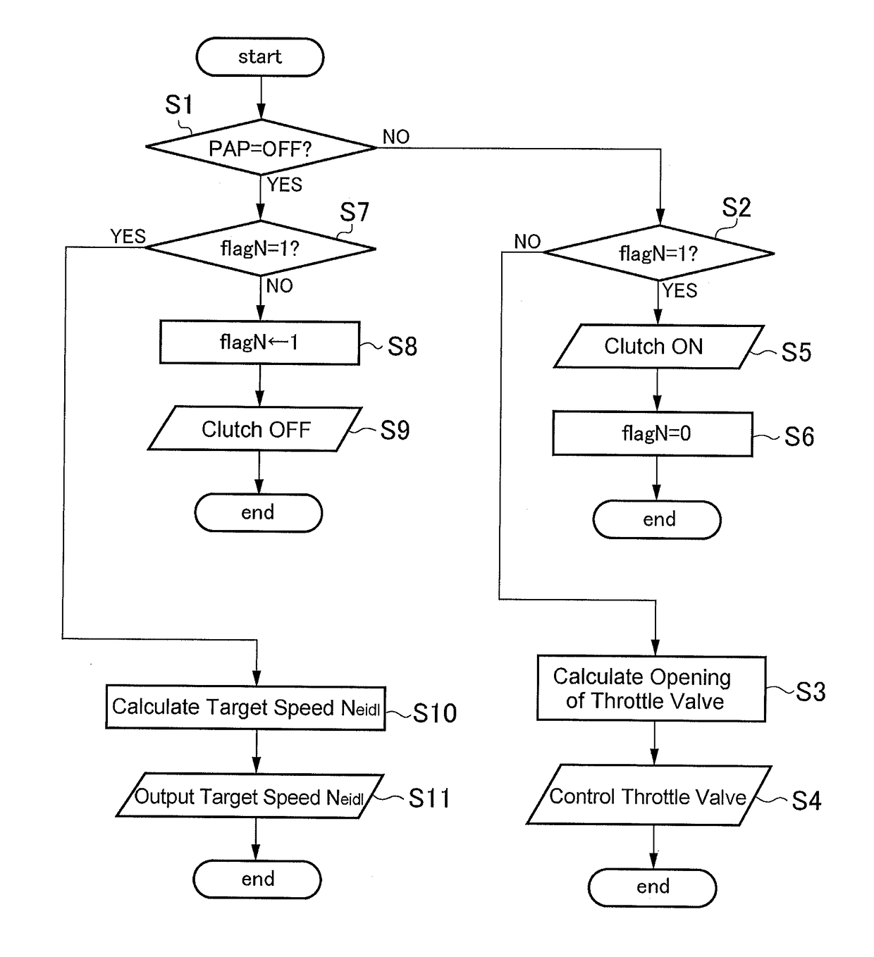
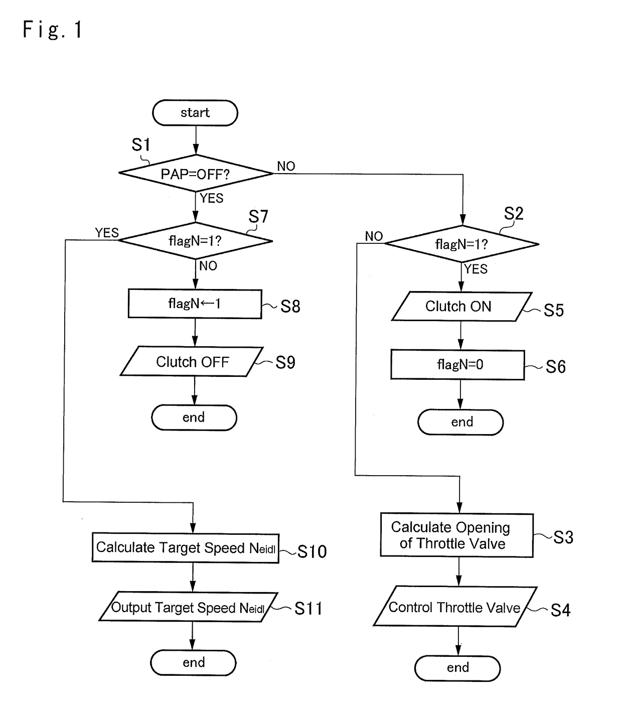
[0015]Thus, according to the present invention, the speed of the prime mover is raised from the idling speed during the coasting if the engagement device is expected to be brought into engagement. That is, the speed of the prime mover can be raised toward to a target speed prior to the engagement of the engagement device so that engagement shocks of the engagement device can be reduced. Therefore, the engagement device is allowed to be brought into engagement without waiting for an increment of the speed of the prime mover. Additionally, since the speed of the prime mover is thus raised beforehand of engagement of the engagement device, a reaction of the torque increasing the speed of the prime mover can be reduced so that the speed of the prime mover can be raised quickly. Consequently, fuel consumption can be reduced. Further, since the engagement device is brought into engagement while increasing the speed of the prime mover, the vehicle can be accelerated or an engine braking force can be applied to the vehicle as soon as bringing the engagement device into engagement. Consequently, the torque of the drive wheels can be increased to a desired level in short time.
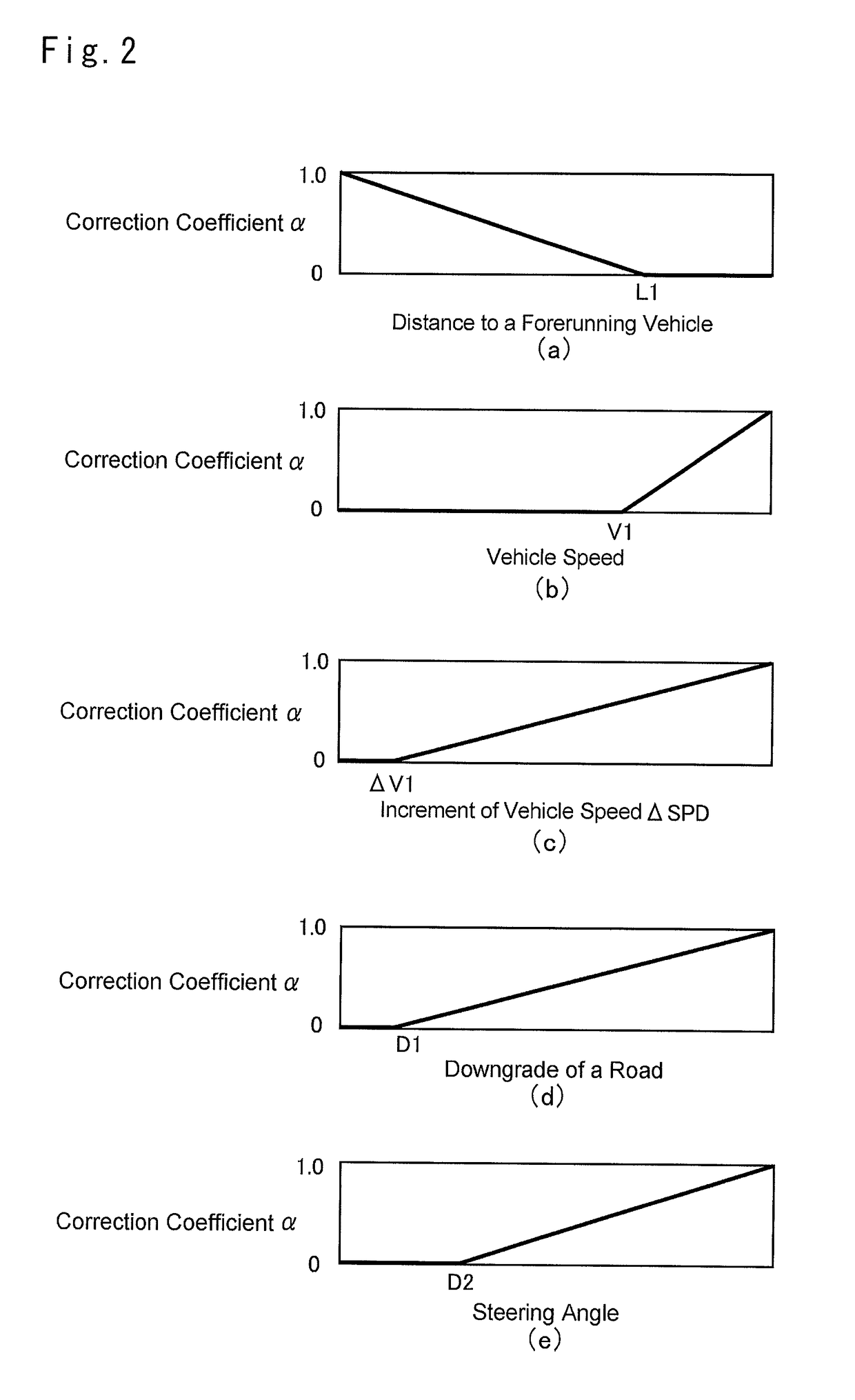
[0016]As described, the speed is of the prime mover is raised in accordance with the degree of probability of engagement of the engagement device. In this case, the speed difference of the prime mover before and after the engagement of the engagement device can be further reduced so that the engagement device is allowed to be brought into engagement more quickly.
[0017]As also described, the speed of the prime mover is raised to the maximum speed thereof in case of engaging the engagement device during coasting. That is, the speed of the prime mover will not be raised excessively during coasting. Therefore, the fuel will not be wasted to increase the speed of the prime mover unnecessarily.

Problems solved by technology

The engine generates not only a power for propelling the vehicle but also an engine braking force resulting from a pumping loss of the engine.
This means that shocks may be caused by the engine braking force if the clutch is immediately brought into engagement upon depression of the accelerator pedal or the brake pedal.
However, when the clutch is brought into engagement, the engine speed is lowered to the idling speed and hence acceleration response would be degraded.
That is, even if the throttle valve supplying fuel to the engine is opened widely to increase the engine speed after engaging the clutch, it would take more time to achieve a desired engine speed due to the inertial mass of the engine, the transmission etc.
Consequently, it will take more time to achieve a desired drive torque transmitted to the drive wheels.

Method used


Image

  • Running control system for vehicle
  • Running control system for vehicle
  • Running control system for vehicle

Examples


Embodiment Construction

)

[0023]Next, a preferred example of the running control system according to the present invention will be explained hereinafter. Referring now to FIG. 5, there is shown a preferred example of a powertrain to which the present invention is applied. As shown in FIG. 5, a powertrain 4 comprises a transmission 3 that transmits power of a prime mover 1 to drive wheels 2 while changing a rotational speed and a torque. For example, a gasoline engine, a diesel engine and etc. may be used as the prime mover (as will be called the “engine” hereinafter) 1. Fuel supply to the engine 1 is controlled in a manner to achieve a desired drive torque by altering an opening degree of a throttle valve 6 according to a depression of an accelerator pedal 5. Specifically, if a depression of the accelerator pedal 5 is increased, an opening degree of the throttle valve 6 is increased to generate larger engine power. By contrast, if a depression of the accelerator pedal 5 is decreased, an opening degree of th...


PUM


Abstract

A running control system for vehicles is provided to reduce engagement shocks of a clutch and to raise the torque of drive wheels quickly upon satisfaction of a condition of engagement of the clutch. In a vehicle to which the running control system is applied, power transmission between an engine and the drive wheels is selectively enabled by the clutch. The running control system is configured to raise a speed of the engine from an idling speed if the clutch is expected to be engaged during coasting where the clutch is in disengagement to interrupt a torque transmission between the engine and the drive wheels.

Description

CROSS-REFERENCE TO RELATED APPLICATION[0001]This is a national phase application based on the PCT International Patent Application No. PCT / JP2012 / 072318 filed Sep. 3, 2012, the entire contents of which are incorporated herein by reference.TECHNICAL FIELD[0002]The present invention relates to a control system for controlling a driving force and a braking force during propelling a vehicle, and more particularly, to a running control system for controlling a coasting of the vehicle.BACKGROUND ART[0003]A prime mover of a vehicle such as an internal combustion engine has to be operated at a speed higher than a self-sustaining speed, and even when the vehicle is stopped, the engine is activated for the purpose of generation and air conditioning. For these purposes, according to the conventional art, the engine is disconnected from a powertrain (or a gear train) by a clutch depending on the situation so that the engine is allowed to be activated to generate a power for electric generation ...

Claims


Application Information

Patent Timeline
Patent Type & Authority Patents(United States)
IPC IPC(8): B60W30/04B60W10/04F16D48/02B60W10/02F16D48/06F02D41/10F02D41/02F02D29/02F02D41/14F02D41/08
CPCB60W10/02B60W10/04F02D29/02F02D41/022F02D41/107F16D48/02F16D48/06B60W2710/02B60W2720/10F02D41/0225F02D41/08F02D2041/1412F02D2200/501F02D2200/702F16D2500/10412F16D2500/3027F16D2500/3067F16D2500/5085F16D2500/70408Y02T10/60
Inventor MITSUYASU, MASAKI
Owner TOYOTA JIDOSHA KK
Learn More