
Coating structure and method

a coating structure and coating technology, applied in the field of coating structure, can solve the problems of limiting the life of components and equipment, and achieve the effect of prolonging the life of articles

Inactive Publication Date: 2012-08-21
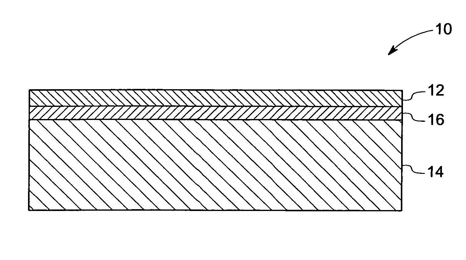
GENERAL ELECTRIC CO
View PDF23 Cites 19 Cited by
  • Summary
  • Abstract
  • Description
  • Claims
  • Application Information

AI Technical Summary

Benefits of technology

"The invention relates to a coating structure that includes an outer coating of aluminum and an interlayer between the substrate and the outer coating. The interlayer may include rare earth metals, transition metals, or noble metals. The interlayer is less responsive to fluorine etching, has a different color, and has different electrical conductivity than the outer coating, which can be used to detect when the article is ready for recoat and protect the substrate from halogen gas penetration. The technical effects of this invention include improved adhesion, durability, and protection of the substrate."

Problems solved by technology

These gases or plasma may attack the components of the coating equipment and may cause erosion.
This erosion may limit the life of the components and of the equipment.

Method used


Image

  • Coating structure and method
  • Coating structure and method
  • Coating structure and method

Examples


example 1

Etch Rate Measurements of Glass Samples

[0048]Five samples are prepared from alumino-silicate glasses with differing concentrations of rare earth metal oxides / transition metal oxide. A stoichiometric amount of aluminum oxide, silicon oxide, and rare earth oxide / transition metal oxide are fused into a layer. No top coat is provided to allow testing of the interlayer etch rate.

[0049]The etch rate of the samples is measured after fluorine reactive ion etching. Table 1 shows the etch rate of Samples 1-5 as measured by gravimetry. Gravimetry involves measuring the weight change of the samples after fluorine reactive ion etching and considering the sample density and surface area. Fluorine reactive ion etching was carried out with NF3 / Ar ratio of 16 / 34 standard cubic centimeters per minute (sccm), chamber pressure of 100 mTorr, at 400 watts for 300 minutes.

[0050]

TABLE 1Etch rate of Samples 1-5Composition (wt %)Etch rateSampleAl2O3SiO2Y2O3CeO2Gd2O3(Å / min)120.135.444.5——2.6215.827.9——56.30.9...

example 2

Etch Rate Measurements of Rare-Earth Oxide and Transition Metal Oxide Bulk Samples

[0051]Samples 6-10 include metal oxide pellets. The metal oxide pellets are prepared by compacting and sintering of the indicated metal oxide powders. Fluorine reactive ion etching was carried out with NF3 / Ar ratio of 16 / 34 standard cubic centimeter per minute (sccm), chamber pressure of 100 mTorr, at 400 watts for 300 minutes.

[0052]The etch rate of Samples 6-10 is measured after fluorine reactive ion etching. Table 2 shows the etch rate of bulk samples 6-10 as measured by gravimetry. Gravimetry involves measuring the weight change of the samples after fluorine reactive ion etching and considering the sample density and surface area.

[0053]

TABLE 2Etch rate of bulk samplesSampleCompositionEtch rate (Å / min)6Y2O30.0 ± 0.47Al2O33.1 ± 0.48HfO29.1 ± 0.29CeO2−0.3 ± 0.3 10 Gd2O3−0.6 ± 0.3 

example 3

Etch Rate Measurements of Metal Oxide Coatings

[0054]Metal oxide coatings are prepared on clean substrates of quartz by sputtering. The conditions of the preparation include the sputtering environment, the flow rate, and the power requirements. The sputtering is carried out in 7% oxygen (balance argon) at 10 microns pressure and 65 cubic centimeters per minute flow rate. Radiofrequency power is 400 watts and 950 volts.

[0055]The thickness of the resulting coating is 350 nanometers plus or minus 150 nanometers. Once prepared, Samples 11-13 are etched. Fluorine reactive ion etching is carried out with NF3 / Ar ratio of 16 / 34 standard cubic centimeter per minute (sccm), and a chamber pressure of 100 mTorr at 400 watts for 300 minutes.

[0056]The etch rate is determined by profilometry comparison. Profilometry involves providing a shallow mask on the sample. The height of the step is measured before fluorine reactive ion etching, and again afterward. The height differential is calculated, and...


PUM

PropertyMeasurementUnit
thicknessaaaaaaaaaa
thicknessaaaaaaaaaa
thicknessaaaaaaaaaa

Abstract

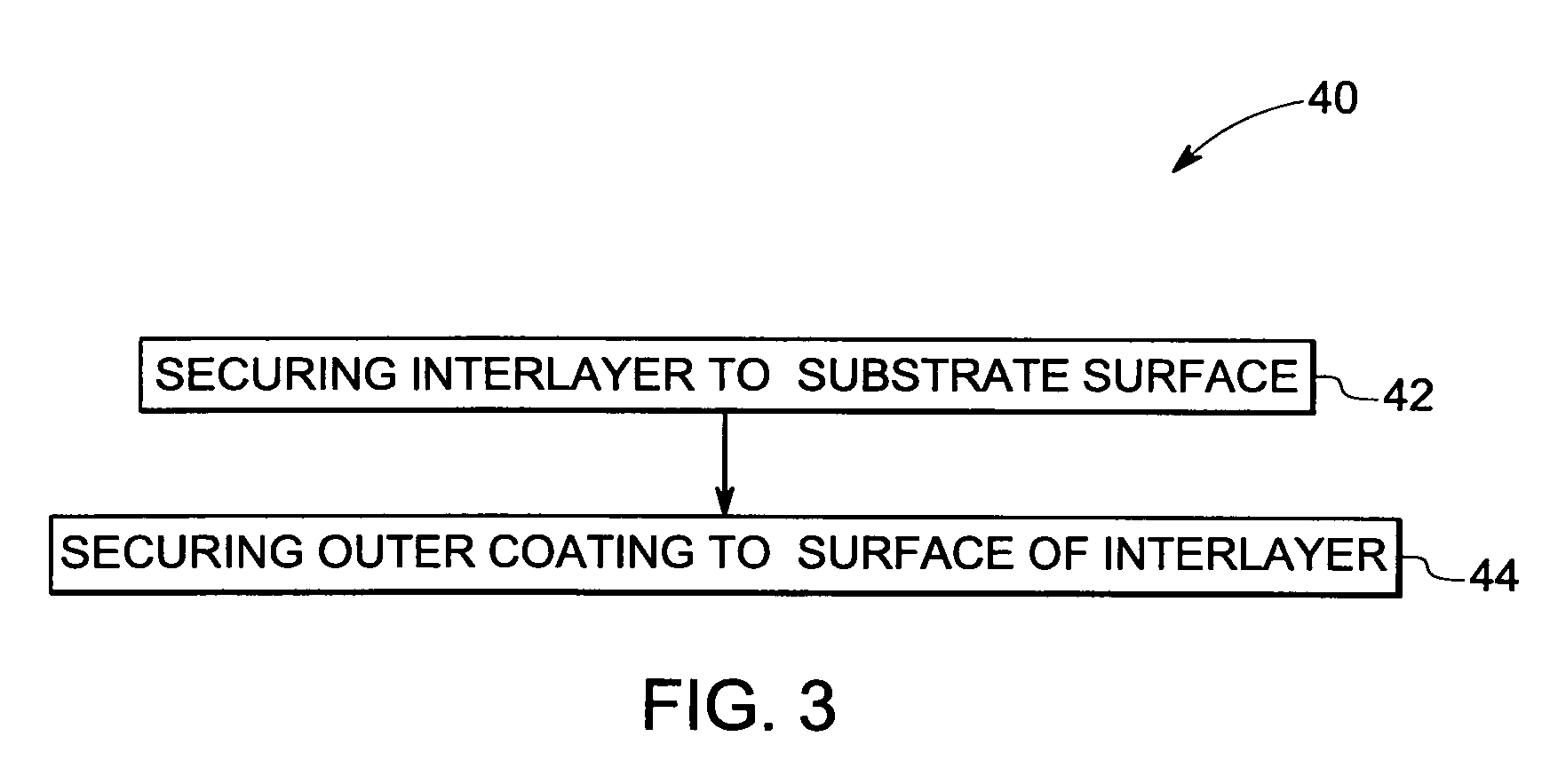
A coating structure including an outer coating comprising aluminum; and an interlayer disposed between a substrate and the outer coating is provided. The interlayer may include a rare earth metal, a transition metal, or a noble metal. The interlayer may have one or more property of being less responsive to halogen etching relative to the outer coating; having a coefficient of thermal expansion that is greater than the coefficient of thermal expansion of the substrate and less than the coefficient of thermal expansion of the outer coating or vice versa; having a color different from the color of the outer coating; having a electrical conductivity different from the electrical conductivity of the outer coating. A method of making is article is provided. The method may include securing an interlayer to a substrate surface, and securing an outer coating to a surface of the interlayer opposite the substrate.

Description

BACKGROUND[0001]The invention includes embodiments that may relate to a coating structure. The invention includes embodiments that may relate to a method of depositing the coating structure.[0002]In wafer production, halogen-based corrosive gases or plasma may be used for purposes of deposition, etching, and cleaning. These gases or plasma may attack the components of the coating equipment and may cause erosion. This erosion may limit the life of the components and of the equipment.[0003]It may be desirable to extend the service life of components and equipment exposed to corrosive atmosphere.BRIEF DESCRIPTION[0004]In one embodiment in accordance with the invention, a coating structure may include an outer coating comprising aluminum and an interlayer disposed between a substrate and the outer coating. The interlayer may include a rare earth metal, a transition metal, or a noble metal.[0005]According to another embodiment, an article may include a substrate; an outer coating; and, a...

Claims


Application Information

Patent Timeline
Patent Type & Authority Patents(United States)
IPC IPC(8): B32B15/04C23C16/00B32B9/00B32B19/00B05D1/36
CPCC04B41/009C04B41/5063C04B41/52C04B41/87C04B41/89C23C14/0617C23C14/22C23C16/303C23C16/4404C23C16/4581C23C16/513C04B41/5031C04B41/4529C04B41/4531C04B41/5064C04B41/5057C04B41/522C04B35/522C04B35/583Y10T428/30H01L21/68757
Inventor IACOVANGELO, CHARLES DOMINICLOU, VICTOR LIENKONG
Owner GENERAL ELECTRIC CO
Learn More