
Pipe fitting

a technology for pipe fittings and fittings, applied in the direction of hose connections, screw threaded joints, mechanical equipment, etc., can solve the problems of difficult and complex manufacture of such fittings, particularly susceptible to structural failure of pipe fittings made of plastic with female pipe threads, etc., to reduce displacement, reduce tensile stress, and prevent excessive force during the tightening of the male part in to the pipe fitting.

Inactive Publication Date: 2012-06-19
UPONOR INNOVATION AB
View PDF9 Cites 3 Cited by
  • Summary
  • Abstract
  • Description
  • Claims
  • Application Information

AI Technical Summary

Benefits of technology

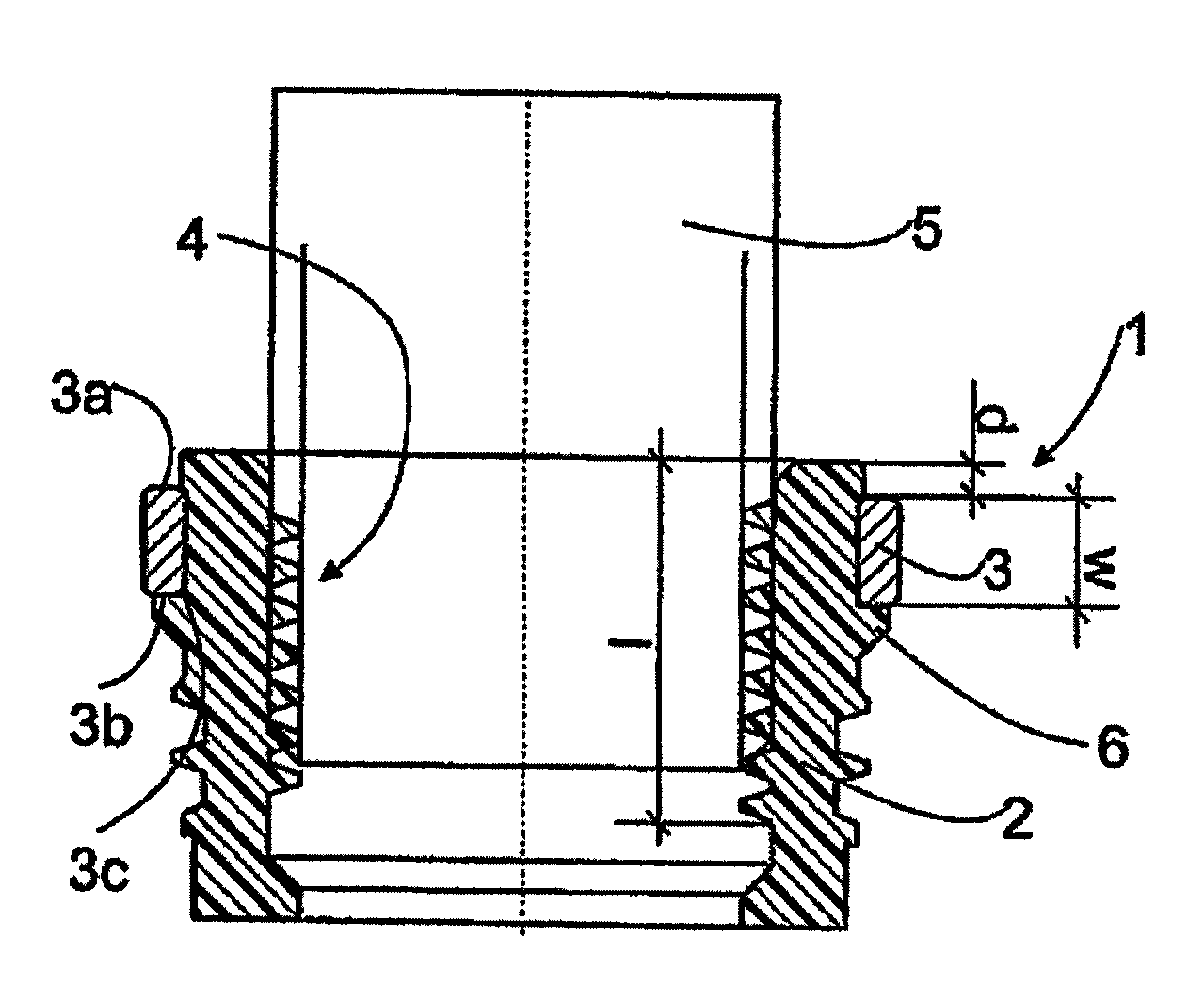
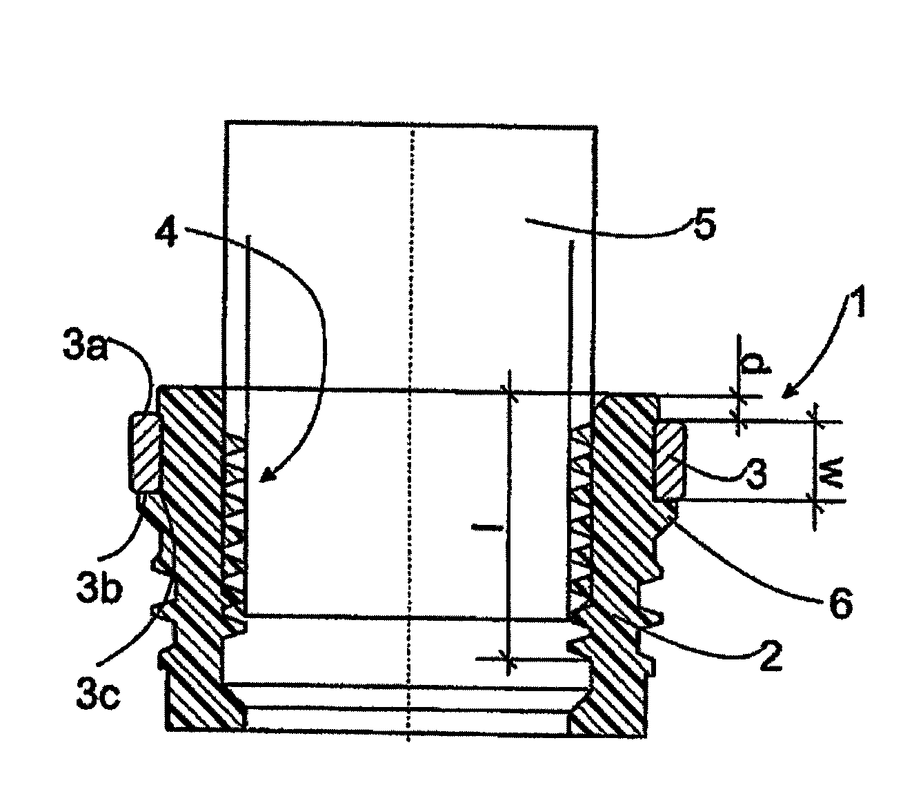
[0007]The described pipe fitting comprises a body made of plastic and a reinforcement ring around the outside of the plastic body. The reinforcement ring is positioned at a distance from the front end of the pipe fitting. The reinforcement ring holds body expansion under control. Thus, the reinforcement ring reduces displacements in the plastic body and in this way reduces tensile stresses developed in the plastic body. Because there is a distance between the reinforcement ring and the front end of the pipe fitting, excessive force during the tightening of the male part in to the pipe fitting can be prevented.
[0008]In one embodiment, the corner of the reinforcement ring located at the back end of the reinforcement ring and against the plastic body of the pipe fitting is rounded. This reduces stress peaks in the plastic body, which are caused by the male part that is to some extent conical. In another embodiment, the plastic body comprises a support rib in the fitting, which supports the back end of the reinforcement ring. This rib also supports the fitting against the stresses caused by the conical male part which bends the reinforcement ring.
[0009]In a yet another embodiment, the plastic body of the fitting is manufactured separately from the reinforcement ring and the reinforcement ring is snapped on the body. Manufacturing the body and the reinforcement ring separately provides the advantages that the pipe fitting is easy to manufacture and it is easier to make the structures and forms of the body and reinforcement ring with the desired properties.

Problems solved by technology

Pipe fittings made of plastic with female pipe threads are particularly susceptible to structural failure.
However, the manufacture of such a fitting is quite difficult and complex.

Method used


Image

  • Pipe fitting
  • Pipe fitting

Examples


Embodiment Construction

[0011]The FIGURE schematically shows a part of a pipe fitting 1. The pipe fitting 1 can be a bend or a T-fitting or a straight fitting or any other suitable pipe fitting.

[0012]The pipe fitting 1 comprises a plastic body 2 and a reinforcement ring 3 positioned around the plastic body 2. The material of the plastic body can be polypropylene PP, polyethylene PE, polyphenyl sulphone PPSU, polysulphone PSU, polyvinylidene fluoride PVDF, polytetrafluorethylene PTFE, polyketones, polyether ketone PEEK, polyacetale POM, or some other plastic material, for example. The reinforcement ring 3 can be made of metal, such as stainless steel, aluminium, copper, or brass. The reinforcement ring 3 can also be made of plastic, for example. The plastic can be reinforced such that it has better properties against elongation than the material of the plastic body 2.

[0013]The plastic body 2 comprises internal threads or female threads 4. When the pipe fitting 1 is used, a part 5 with male threads or a male...


PUM

PropertyMeasurementUnit
inner diameteraaaaaaaaaa

Abstract

The pipe fitting comprises a plastic body (2) and a reinforcement ring (3) around the outside of the plastic body (2). The reinforcement ring (3) holds the body expansion under control. The reinforcement ring (3) is positioned at the distance (d) from the front end of the pipe fitting (1).

Description

CROSS-REFERENCE TO RELATED APPLICATIONS[0001]This application is the National Stage of International Application No. PCT / FI2007 / 050292 filed May 23, 2007, which claims the priority of European Application No. 06114575.1, filed on May 26, 2006. The contents of both applications are hereby incorporated by reference in their entirety.BACKGROUND OF THE INVENTION[0002]The invention relates to a pipe fitting comprising a plastic body and a reinforcement ring around the outside of the plastic body.[0003]Pipe fittings having internal taper threads or female threads are commonly used in the plumping industry. Parts having male pipe threads are threaded into female pipe threads in the fitting to form a pipe joint. Pipe fittings made of plastic with female pipe threads are particularly susceptible to structural failure. It is known to solve this problem by placing a reinforcement ring around the outside of the female pipe fitting to restrict and / or inhibit expansion and splitting of the pipe f...

Claims


Application Information

Patent Timeline
Patent Type & Authority Patents(United States)
IPC IPC(8): F16L15/00
CPCF16L47/16F16L15/08
Inventor LARSSON, THOMASSMAHL, JARMO
Owner UPONOR INNOVATION AB
Learn More