Method of granulation with a fluidized bed granulator
a technology of fluidized bed and granulator, which is applied in the direction of manufacturing tools, natural mineral layered products, and plastic layered products, etc., can solve the problems of increasing pressure loss, difficult to make uniform products in the transverse direction, and irregular products, so as to reduce the size of blowers, ducts, etc., and achieve sufficient linear velocity of fluidization. , the effect of small siz
- Summary
- Abstract
- Description
- Claims
- Application Information
AI Technical Summary
Benefits of technology
Problems solved by technology
Method used
Image
Examples
reference example 1
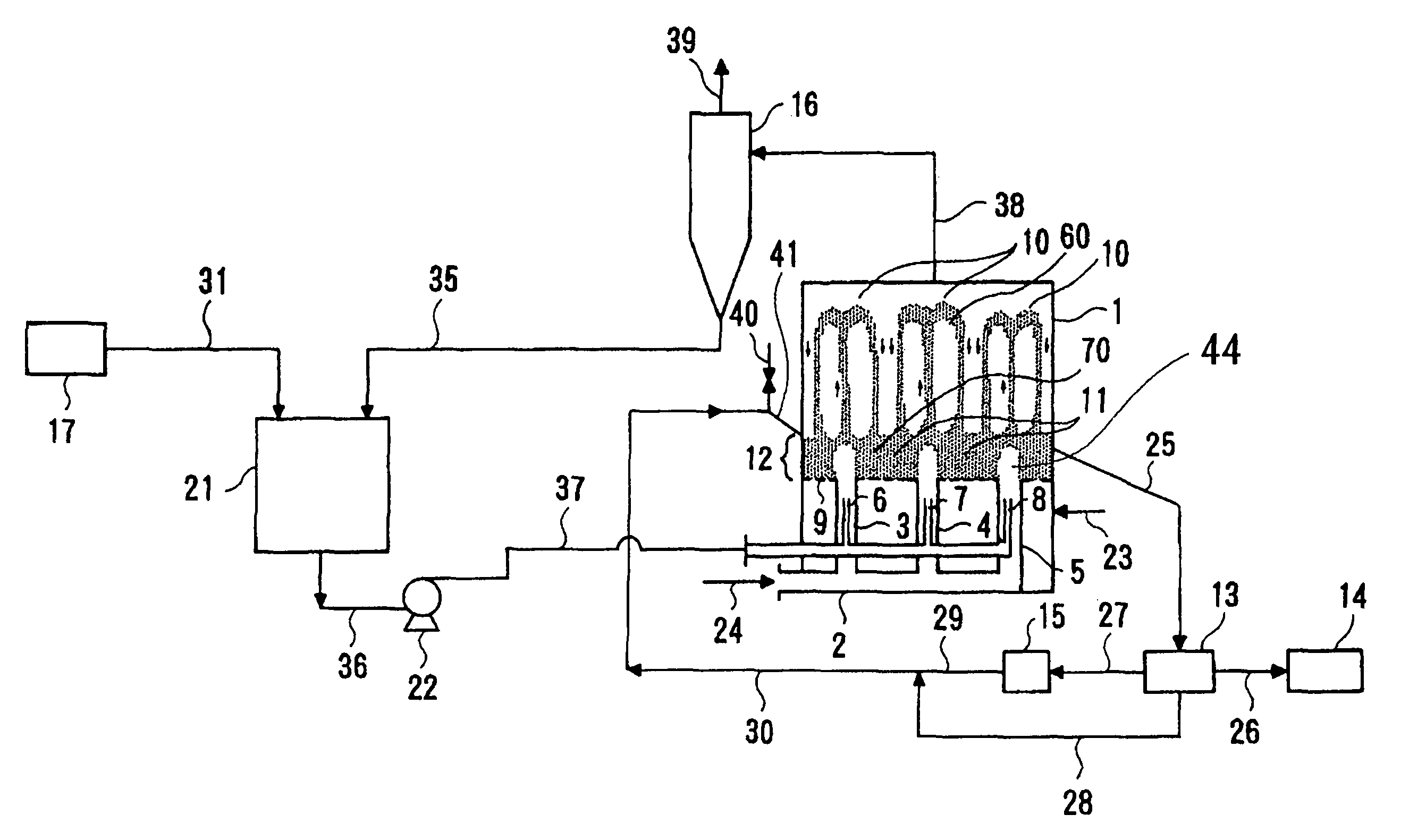
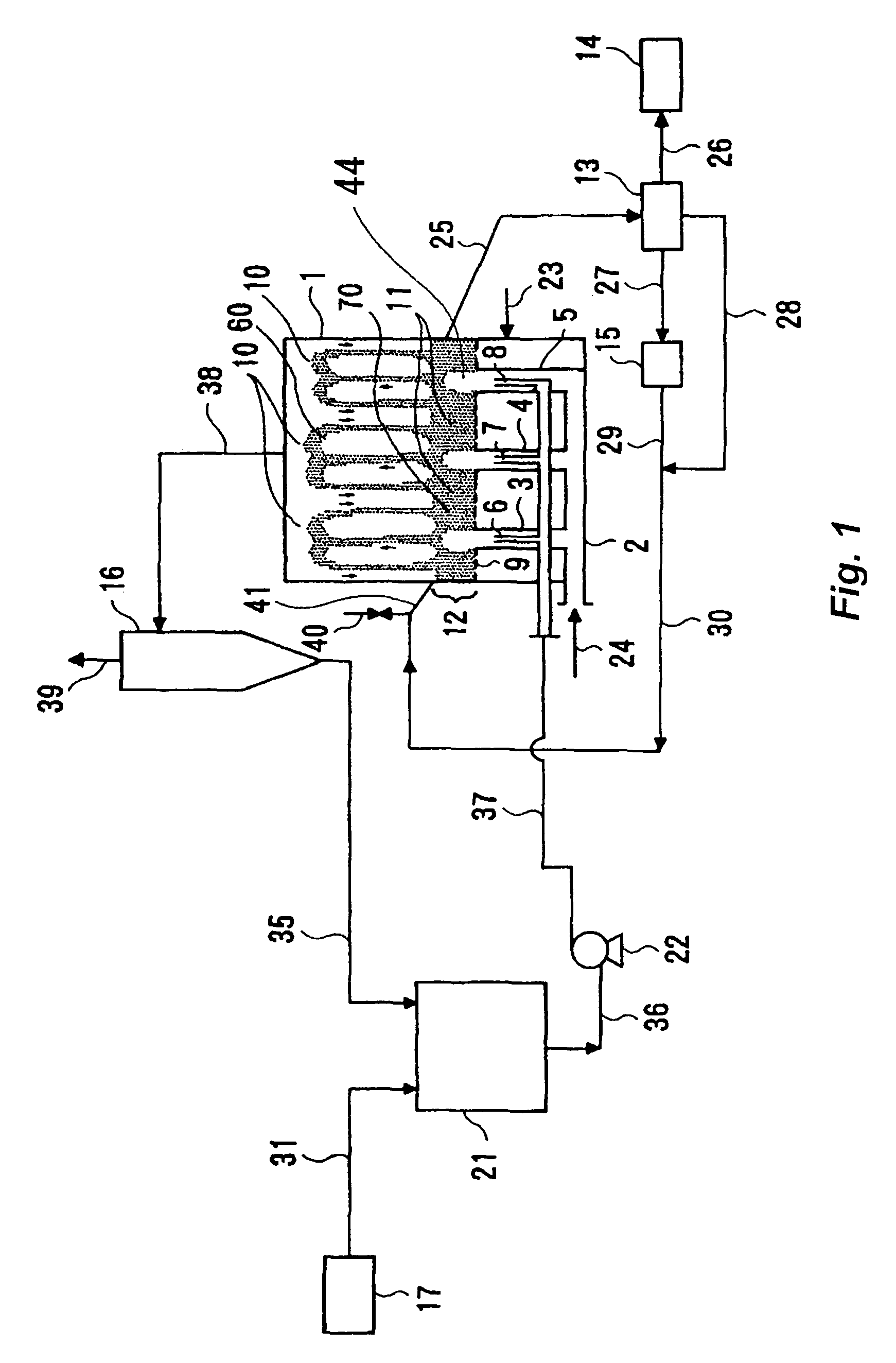
[0074]Urea granules were formed in a urea granulation facility of a daily output of 2,000 tons, according to the same flow as shown in FIG. 1. The urea seed particles are fed into the granulator 1 through a line 30. The air is supplied through a duct 24 and jetted upward in the spouted bed 44 at a flow velocity of 20 m / s. The upward air flow lifts the seed particles up, to form the spouted bed. Simultaneously, separate air is fed through a line 23 to the space under the bottom floor 9, the separate air passes through the bottom floor openings, and then rises upward in the fluidized bed at a flow velocity of 1.9 to 2.2 meter / sec. The air flow fluidizes the seed particles, to form the fluidized bed. A 95% aqueous urea solution discharged from a concentrator 21 is pressurized to 1.2 MPaG by a pump 22, and sprayed upward into the spouted bed 44 in the granulator 1 at a flow rate of 1.3 tons per hour per spray nozzle (represented by the referential numbers 6, 7 and 8 in the figure(s), bu...
reference example 2
[0075]Urea particles were granulated in a urea granulator with a daily output of 1,700 tons in the same flow as that in Reference Example 1, except that the air flow velocity in the fluidized bed was changed to 2.4 to 2.5 meters per second. The indefinite-shaped urea content in the product 14 was determined to be 36 mass %, as shown in Table 1, which was remarkably lower than that in Reference Example 1.
[0076]
TABLE 1ReferenceReferenceExample 1Example 2Facility capacityt / d2,000 1,700 Spouting-pipe nozzleRectangularRectangulararrangementSpouted-air flowm / s2020velocityFluidizing-air flowm / s1.9 to 2.22.4 to 2.5velocityFluidized bed heightm 0.3 0.3Content of Indefinite%5536shaped product
example 1
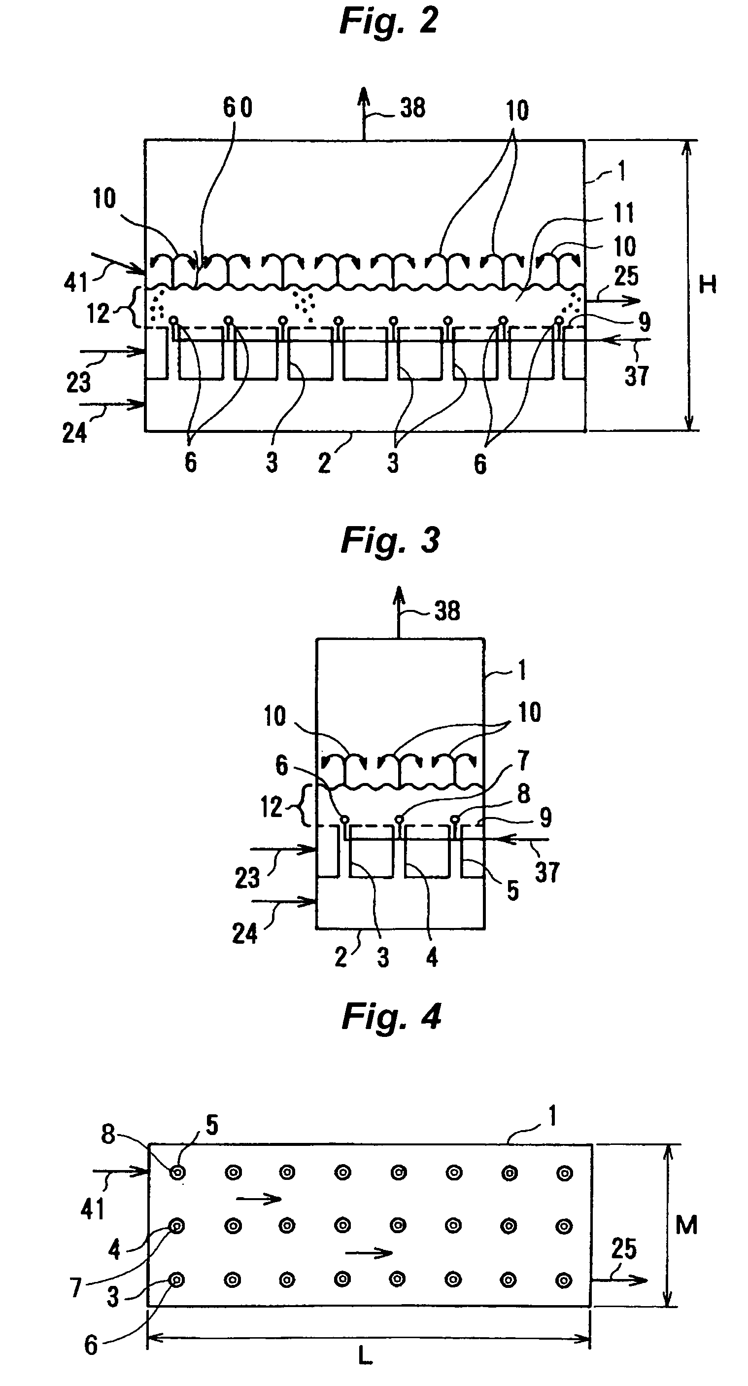
[0078]The spouting-pipe nozzle configuration was changed to the triangular arrangement, as a result the dimension of the bottom floor was 3.3 m×6.68 m and the number of spray nozzle rows was 15. The linear velocity in the fluidization of the air and others are summarized in Table 2, similar to Comparative Example 1. As shown in Table 2, the reduction in size and increase in the number of rows were achieved at the same time in Example 1.
PUM
| Property | Measurement | Unit |
|---|---|---|
| linear velocity | aaaaa | aaaaa |
| diameter | aaaaa | aaaaa |
| temperature | aaaaa | aaaaa |
Abstract
Description
Claims
Application Information
 - R&D
- Intellectual Property
- Life Sciences
- Materials
- Tech Scout
- Unparalleled Data Quality
- Higher Quality Content
- 60% Fewer Hallucinations
Browse by: Latest US Patents, China's latest patents, Technical Efficacy Thesaurus, Application Domain, Technology Topic, Popular Technical Reports.
© 2025 PatSnap. All rights reserved.Legal|Privacy policy|Modern Slavery Act Transparency Statement|Sitemap|About US| Contact US: help@patsnap.com


