
Lubricating device with lubricating pinion

a technology of lubricating device and gearwheel, which is applied in the direction of engine lubrication, gear lubrication/cooling, liquid fuel engine, etc., can solve the problems of irregular and uneven lubricant application on the gearwheel, and sometimes insufficient lubricant supply, so as to achieve simple design and improve the distribution of lubricant

Active Publication Date: 2012-06-12
LINCOLN GMBH
View PDF12 Cites 19 Cited by
  • Summary
  • Abstract
  • Description
  • Claims
  • Application Information

AI Technical Summary

Benefits of technology

[0003]The present invention, in contrast, is based on the problem of making available a lubricating device of the above type that has a very simple design and makes it possible to achieve an improved distribution of the lubricant on a gearwheel to be lubricated.
[0004]According to the invention, this problem is essentially solved in that the teeth of the external toothing of the lubricant transfer pinion have a tooth flank profile that is shortened in comparison to an involute toothing, wherein the addendum and / or the width of the tooth flanks in the circumferential direction are reduced in a tooth flank section that lies radially outside the reference circle. In order to reduce the addendum, it is proposed to reduce, in particular, the thus far existing tip of the tooth. In this case, the addendum is defined as half the difference between the outside diameter of the lubricant transfer pinion and the reference diameter of the lubricant transfer pinion. In other words, the addendum refers to the height of the area of each tooth that protrudes radially outward over the reference circle. In an involute toothing, this is usually a pointed tooth area. If this addendum is reduced in comparison to the addendum of an involute toothing, the depth of penetration of the teeth of the lubricant transfer pinion into the base area of the gearwheel to be lubricated is reduced. It was surprisingly determined that this results in a significantly improved distribution of the lubricant in the areas that are subjected to higher tribological stresses and prevents the undesirable accumulation of the lubricant in the base area of the gearwheel to be lubricated. This applies analogously to a reduction of the width of the tooth flanks in the circumferential direction in a tooth flank section that lies radially outside the reference circle, and therefore also makes it possible to prevent an irregular and uneven application of the lubricant onto the gearwheel to be lubricated and, in particular, the accumulation thereof in the base area of the teeth of gearwheel to be lubricated.

Problems solved by technology

Consequently, the lubricant is irregularly and unevenly applied onto the gearwheel to be lubricated and, in particular, accumulates in the base area of the teeth of the gearwheel to be lubricated.
In addition, the lubricant supply is sometimes insufficient in the area of the contacting tooth flanks that is subjected to high tribological stresses.

Method used


Image

  • Lubricating device with lubricating pinion
  • Lubricating device with lubricating pinion
  • Lubricating device with lubricating pinion

Examples


Embodiment Construction

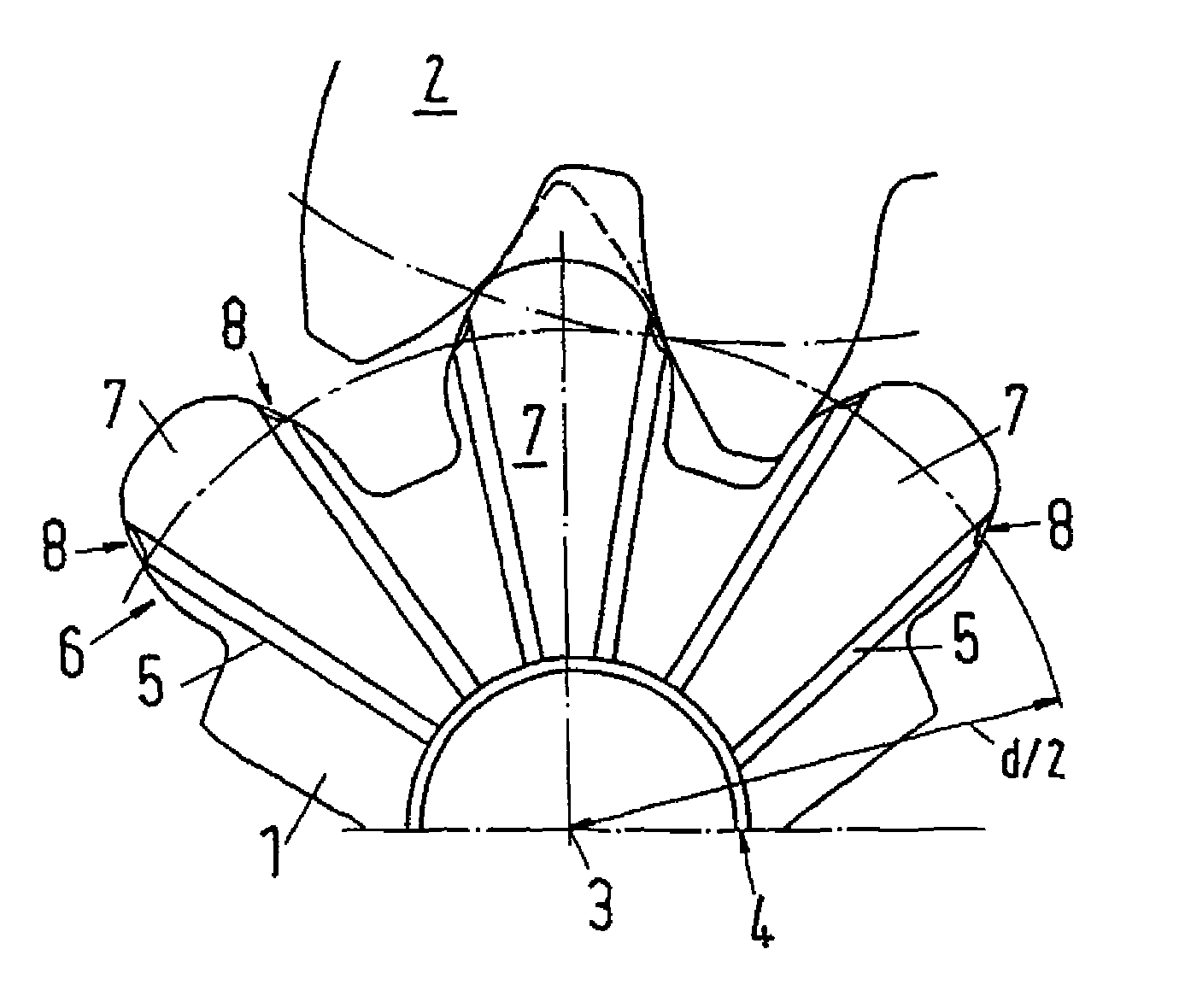
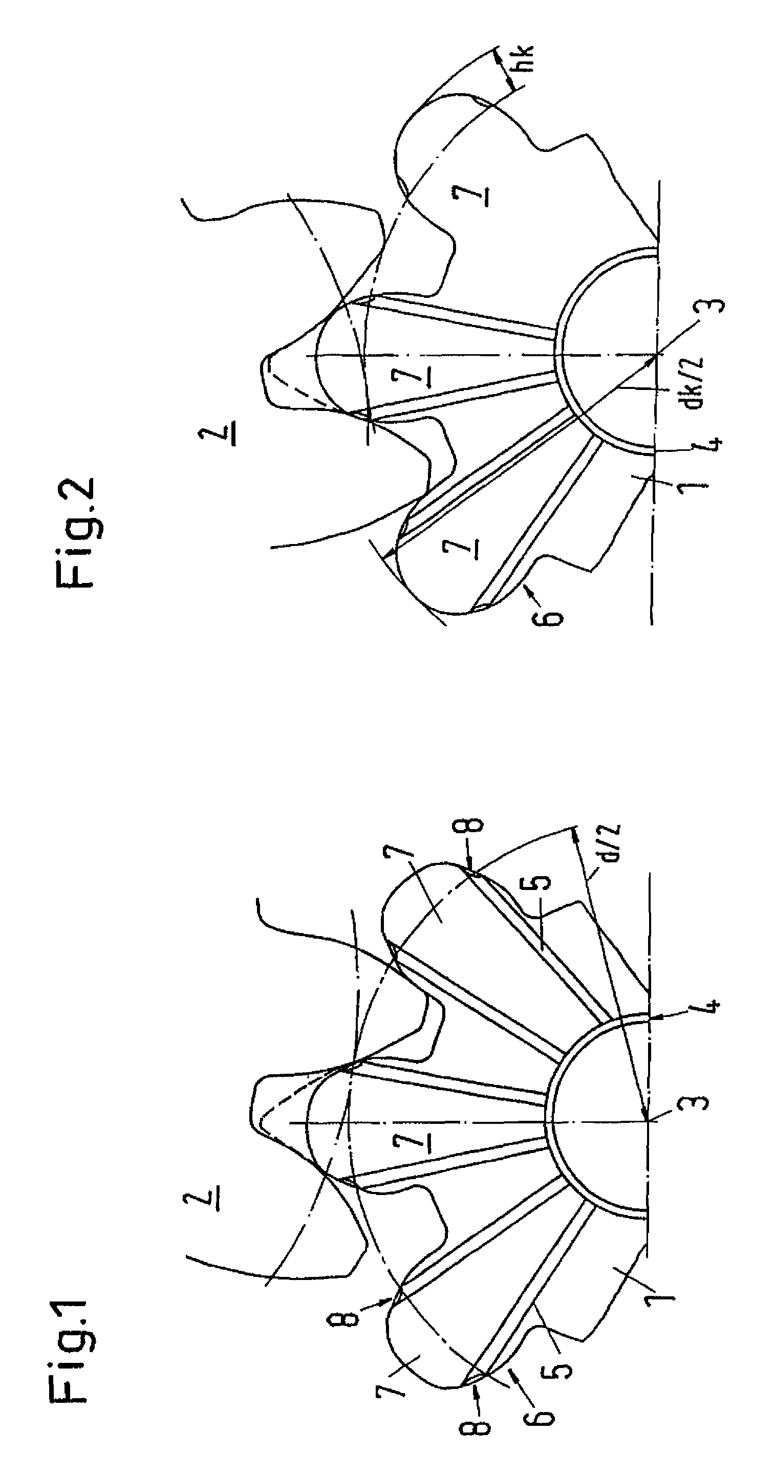
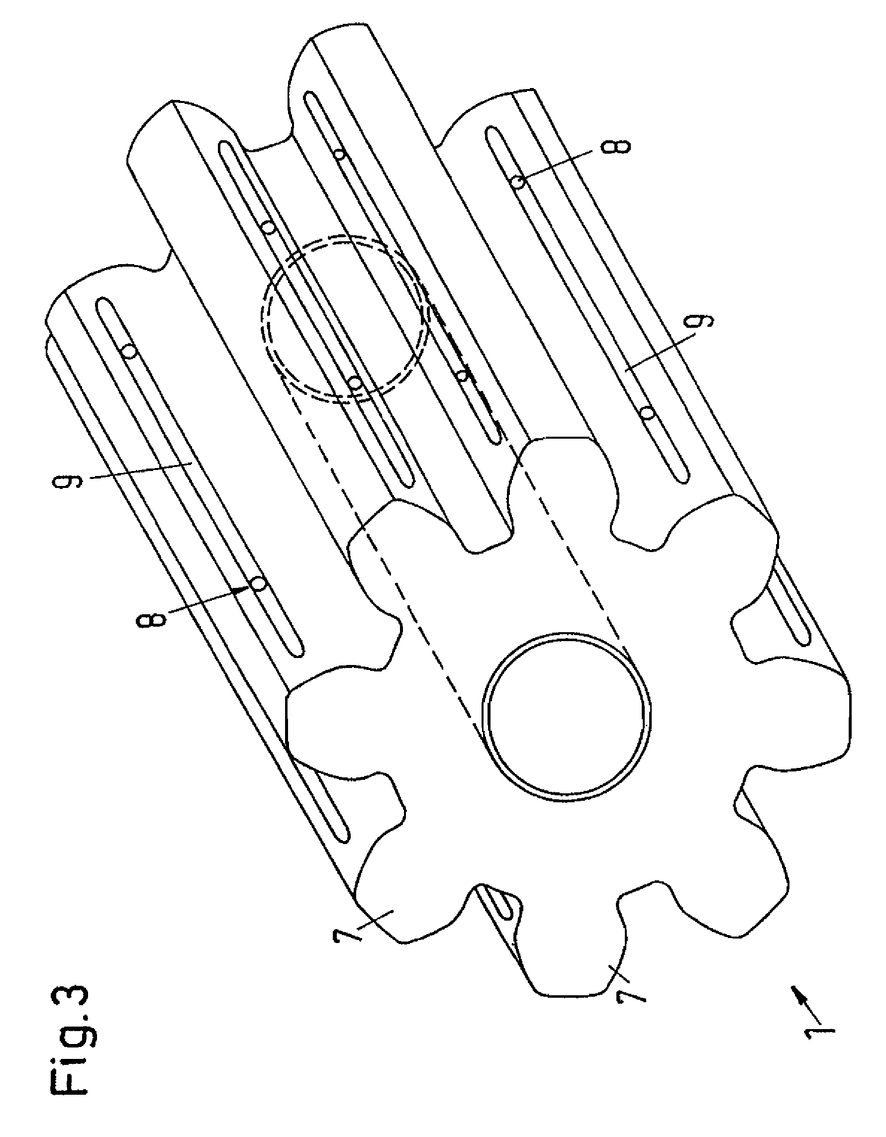
[0012]The figures show parts of a lubricant transfer pinion 1 of a lubricating device that has a reference diameter d. The lubricant transfer pinion 1 meshes with a gearwheel 2 to be lubricated that features an involute toothing and also is only illustrated in part in the figures.

[0013]A lubricant supply line 4 is arranged in the area of the axis 3 of the lubricant transfer pinion 1, wherein lubricant conduits 5 that extend substantially in the radial direction originate at said lubricant supply line and each lead into a respective lubricant outlet 8 in the tooth flanks 6 of the teeth 7 of the lubricant transfer pinion 1. According to FIG. 1, the lubricant outlets 8 lie substantially in the area of the reference circle. In FIG. 1, the lubricant outlet of the lubricant transfer pinion 1 arranged in the right tooth flank contacts the gearwheel 2 to be lubricated, whereas the lubricant transfer pinion 1 in FIG. 2 was additionally turned in the clockwise direction such that the lubrican...


PUM


Abstract

Described is a lubricating device with at least one lubricating pinion for applying a lubricant, in particular grease, which is for example fed through a lubricant line by a lubricant pump from a reservoir, to at least one gearwheel or the like, wherein the lubricating pinion has an outer toothing into which at least one lubricant outlet opens out. The teeth of the outer toothing of the lubricating pinion have a shortened tooth flank profile in relation to an involute toothing, wherein the addendum and / or the width of the tooth flanks in the peripheral direction are reduced in a tooth flank section which is situated radially outside the reference circle.

Description

BACKGROUND OF THE INVENTION[0001]The invention pertains to a lubricating device with at least one lubricant transfer pinion for applying onto at least one gearwheel a lubricant, particularly grease that is transported, for example, from a reservoir through a lubricant conduit by a lubricant pump, wherein the lubricant transfer pinion features external teeth with at least one lubricant outlet.[0002]A device of this type for lubricating gearwheels is known, for example, from DE 201 21 923 U1. The lubricant transfer pinion that is referred to as a crown gear module in this publication has the external contour of a conventional gearwheel with involute toothing. When this known lubricant transfer pinion meshes with a gearwheel to be lubricated, the tip area of the teeth of the lubricant transfer pinion that lies radially outside the reference circle engages into the base area of the teeth of the gearwheel to be lubricated that lies radially inside the reference circle. Consequently, the ...

Claims


Application Information

Patent Timeline
Patent Type & Authority Patents(United States)
IPC IPC(8): F16H57/04
CPCF04C2/084F04C15/0088F16H55/088F16N13/20Y10T74/19995F16H57/0495F16H57/0431F16H55/08F16H57/04
Inventor PALUNCIC, ZDRAVKOSCHOENFELD, ANDREAS
Owner LINCOLN GMBH
Learn More