
TMR read head structures with differential stripe heights

a read head and stripe technology, applied in the field of magnetic transducers, can solve the problems of reducing the utilization factor, increasing the magnetic noise, and posing a fundamental limit to the signal-to-noise ratio (snr), so as to increase the read sensitivity or utilization factor, and reduce the magnetic noise

Inactive Publication Date: 2012-06-05
WESTERN DIGITAL TECH INC
View PDF31 Cites 157 Cited by
  • Summary
  • Abstract
  • Description
  • Claims
  • Application Information

AI Technical Summary

Benefits of technology

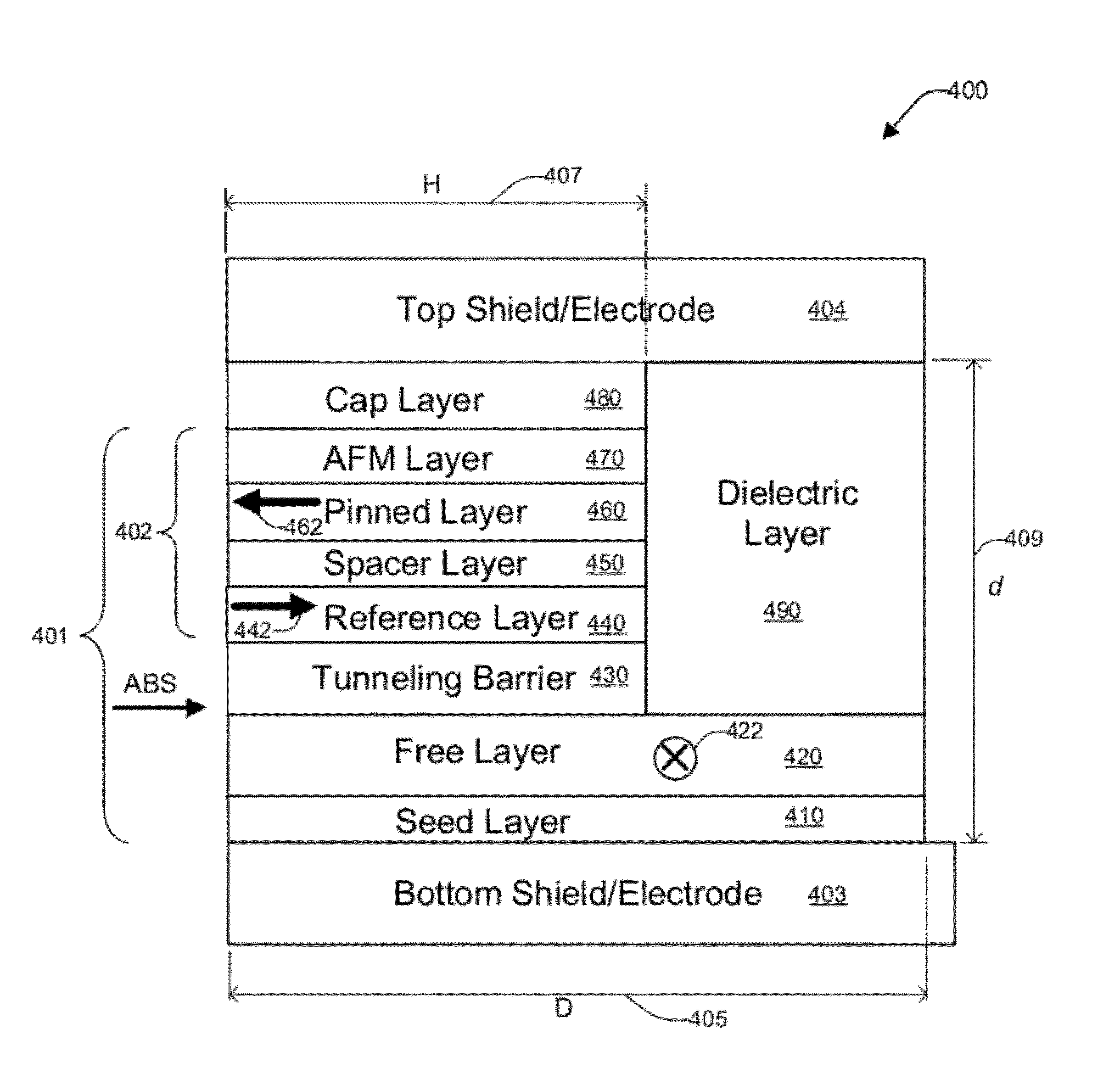
The patent text describes a new structure for a TMR read sensor that reduces magnetic noise and increases read sensitivity. This structure has a free layer with a larger stripe height than the current path stripe height, which drastically reduces magnetic noise. The text also describes a double lift-off integration process that can be used to produce this structure. The technical effect of this invention is that it allows for high recording density applications, such as 1000 to 1500 Gbit / in2.

Problems solved by technology

It is believed that the magnetic noise poses a fundamental limit to signal-to-noise ratio (SNR) of a magnetic recording system.
One of major problems in future generation of TMR read sensor devices is to obtain the highest ΔR / R of the magneto-resistance or high utilization factor while further reducing the magnetic noise.
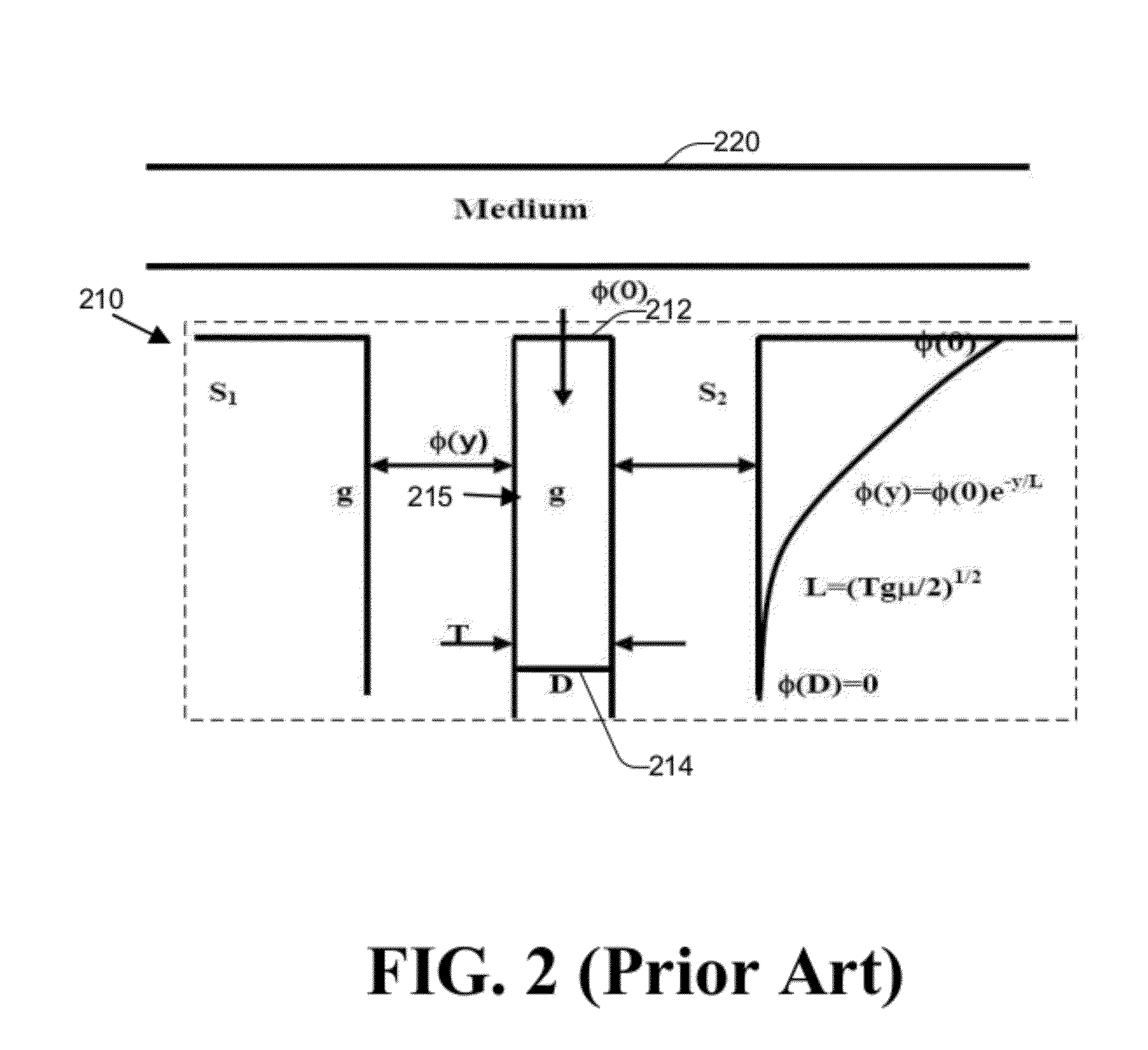
However, the magnetic noise increases as the read sensor's dimension is scaled down, and the enhancement of permanent magnet (PM) strength leads to reduction of the utilization factor.
However, as the read sensor dimensions are further reduced, the magnetic noise issue becomes more and more significant in terms of the read sensor's SNR performance.

Method used


Image

  • TMR read head structures with differential stripe heights
  • TMR read head structures with differential stripe heights
  • TMR read head structures with differential stripe heights

Examples


Embodiment Construction

[0016]In the following detailed description, numerous specific details are set forth to provide a full understanding of the present invention. It will be apparent, however, to one ordinarily skilled in the art that the present invention may be practiced without some of these specific details. In other instances, well-known structures and techniques have not been shown in detail to avoid unnecessarily obscuring the present invention.

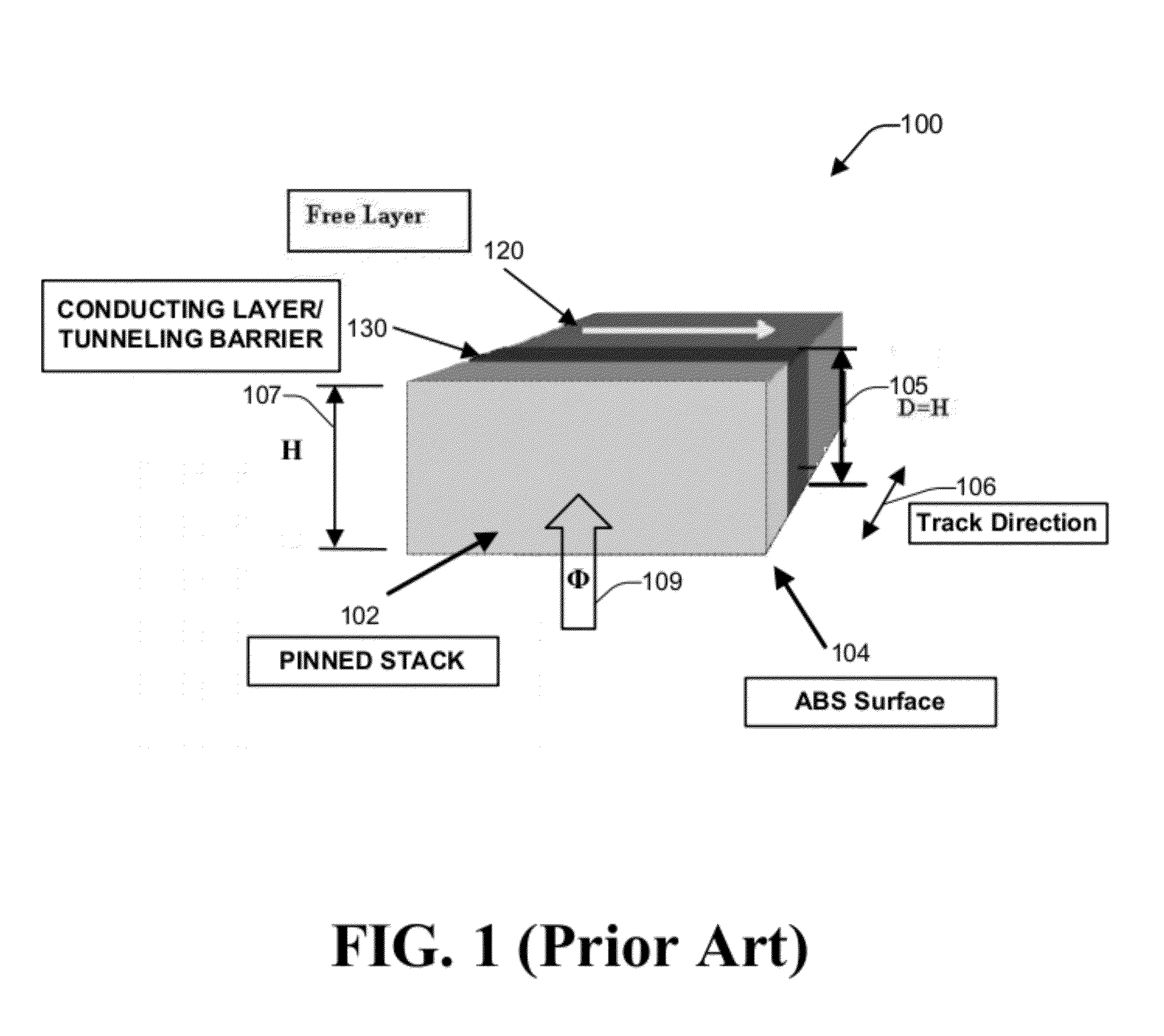
[0017]FIG. 1 is a perspective view of a conventional TMR sensing element 100 (e.g., a CPP read element) which has a uniform stripe height across a track direction 106. The conventional TMR sensing element 100 has a plurality of magnetic layers including a free layer 120, a pinned stack 102, and a tunneling barrier layer 130 disposed between the free layer 120 and the pinned stack 102. The free layer 120 has a free layer stripe height (D) 105, and the pinned stack 102 has a current path stripe height (H) 107. In the conventional TMR sensing element 100, th...


PUM

PropertyMeasurementUnit
sizeaaaaaaaaaa
tunneling magnetoresistanceaaaaaaaaaa
stripe heightaaaaaaaaaa

Abstract

A tunneling magnetoresistance (TMR) read head and a method of producing the same are disclosed. A free layer having a free layer stripe height is provided, the free layer having a first side and a second side. A tunneling barrier layer is formed adjacent to the first side of the free layer, the tunneling barrier layer having a first side and a second side, the second side of the tunneling barrier layer facing the first side of the free layer. A pinned stack is formed adjacent to the first side of the tunneling barrier layer. The pinned stack comprises at least one magnetic layer having a current path stripe height that is less than the free layer stripe height.

Description

FIELD OF THE INVENTION[0001]The present invention generally relates to magnetic transducers and, in particular, relates to TMR read head structures with differential stripe heights.BACKGROUND OF THE INVENTION[0002]Tunnel magnetoresistance (TMR) read sensors, such as current-perpendicular-to-plane (CPP) TMR read sensors, are frequently employed as magnetoresistive sensors in the magnetic read heads of hard disk drives. Thermal magnetization fluctuations, also known as magnetic noise, in the ferromagnetic free layer of TMR read sensors have been recognized as a significant source of intrinsic head noise. In a TMR read sensor, the magnetic noise scales inversely with the read sensor's volume. It is believed that the magnetic noise poses a fundamental limit to signal-to-noise ratio (SNR) of a magnetic recording system.[0003]One of major problems in future generation of TMR read sensor devices is to obtain the highest ΔR / R of the magneto-resistance or high utilization factor while furthe...

Claims


Application Information

Patent Timeline
Patent Type & Authority Patents(United States)
IPC IPC(8): G11B5/33
CPCG01R33/098G11B5/3909G11B5/398H01L43/08H01L43/12H10N50/10H10N50/01
Inventor LI, SHAOPINGGUO, YIMINLIU, FENGZHANG, WEIMAO, SINING
Owner WESTERN DIGITAL TECH INC
Learn More