
Perpendicular magnetic recording medium with improved magnetic anisotropy field

a technology of magnetic anisotropy and recording media, applied in the field of perpendicular magnetic recording media, can solve the problems of short supply and high cost of ru, and achieve the effects of excellent crystallographic c axis orientation, high hc, and high h

Inactive Publication Date: 2010-02-11
WD MEDIA
View PDF3 Cites 139 Cited by
  • Summary
  • Abstract
  • Description
  • Claims
  • Application Information

AI Technical Summary

Benefits of technology

[0007]A magnetic recording medium comprises first, second and third underlayers and a magnetic recording layer. The magnetic recording layer is a HCP material typically comprising one or more magnetic Co alloy layers. The underlayers promote vertical orientation of the C axis of the magnetic layers and enhance grain isolation, resulting in an increase in the coercivity of the magnetic layers. The first underlayer is a seed layer that typically comprises amorphous Ta or a Ta alloy and is non-magnetic.
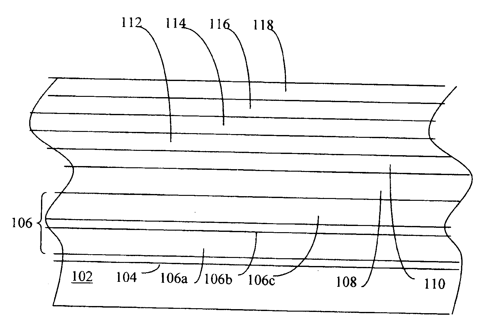
[0009]The third underlayer is typically a non-magnetic HCP material, and can comprise Ru (including a Ru-based alloy) or a Co-based alloy that can comprise one or more of Cr, Ta, W, Mo, Nb, Ti, Hf, Y, V, Sr, and Ni. We have discovered that by using these materials we can achieve good crystal growth (e.g. with vertical orientation of the C axis of the magnetic layer) and high magnetic coercivity while using less Ru than medium 10. We have also discovered that we can achieve reduced transition noise and improved thermal stability.
[0011]In one embodiment, the medium comprises a substrate and a SUL formed underneath the underlayers. It is desirable to minimize the thickness of the layers between the SUL and the magnetic layers. Of importance, by using a seed layer comprising Ta and a second underlayer comprising a NiW alloy, we are able to achieve this objective.
[0013]As mentioned above, we can achieve a high Hc owing to the unique combination of underlayers comprising Ta and NiW, for the case of a single or a bottom magnetic layer, we can achieve a high Hc of about 7 kOe even when the bottom magnetic recording layer is thin, e.g. 7 nm, while simultaneously achieving excellent crystallographic C axis orientation. A benefit of the high Hc in the thin bottom magnetic recording layer is the reduction of transition noise and improved thermal stability in dual magnetic recording layers. We have been able to achieve a medium signal-to-noise ratio SNRme improvement of 0.6 to 1.3 dB compared to conventional underlayer structures.

Problems solved by technology

Unfortunately, formation of amorphous oxide grain boundaries can degrade the vertical orientation of the magnetization and cause broad switching field distribution in layer 18, as discussed in H. S. Jung et al., “Effect of Oxygen Incorporation on Microstructure and Media Performance in CoCrPt—SiO2 Perpendicular Recording Media”, IEEE Transactions on Magnetics, Vol. 43, No. 2, pp.
Unfortunately, Ru is expensive and in short supply.

Method used


Image

  • Perpendicular magnetic recording medium with improved magnetic anisotropy field
  • Perpendicular magnetic recording medium with improved magnetic anisotropy field
  • Perpendicular magnetic recording medium with improved magnetic anisotropy field

Examples


Embodiment Construction

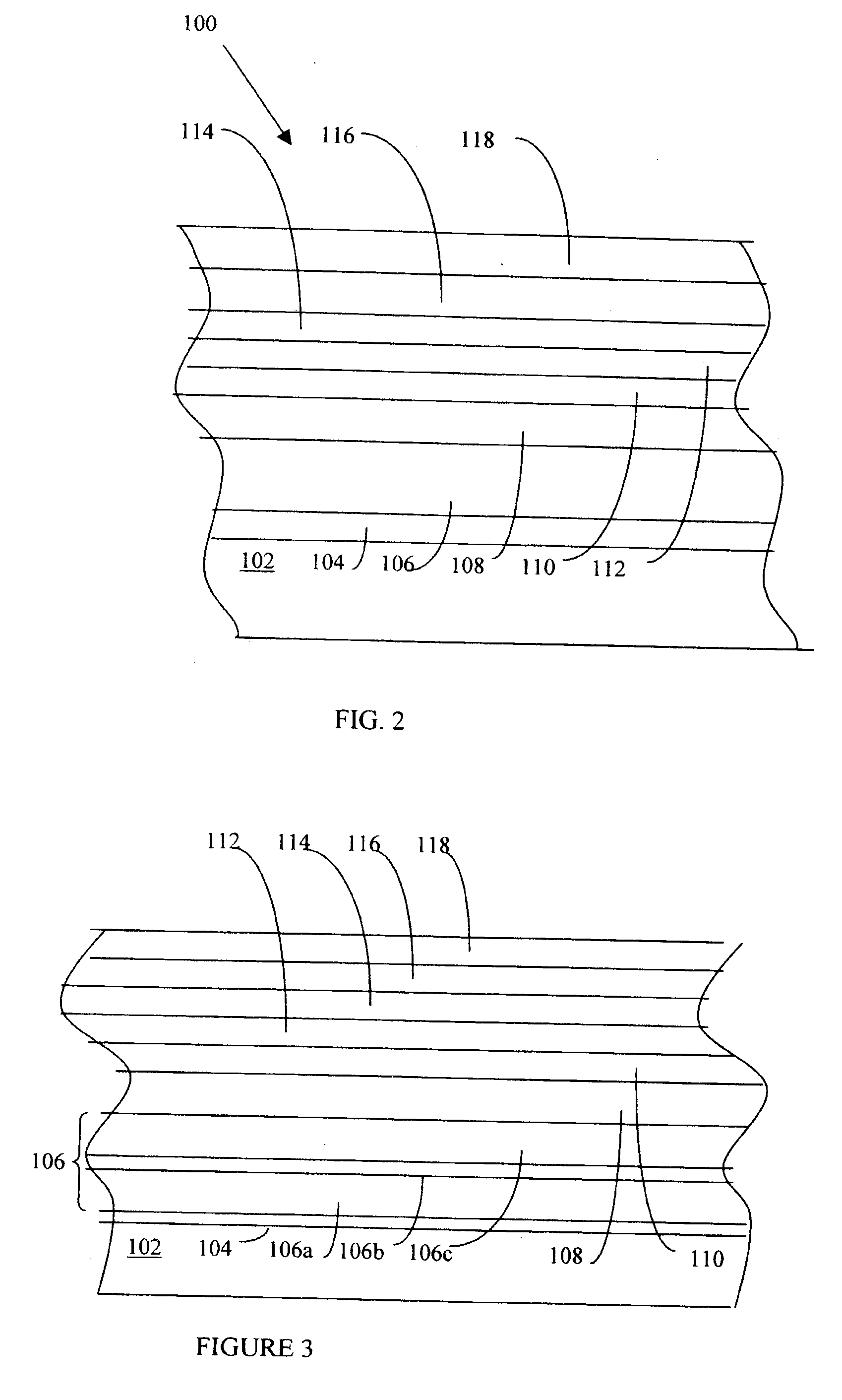
[0031]Referring to FIG. 2, a magnetic recording medium 100 comprises a substrate 102, an adhesion layer 104, a SUL 106, a seed layer 108, a non-magnetic layer 110, a HCP non-magnetic layer 112, a bottom magnetic recording layer 114, a capping magnetic recording layer 116 and a protective carbon overcoat 118. A thin lubricant layer such as perfluoropolyether (not shown) can be applied to the top surface of overcoat 118. Although FIG. 2 only shows the various layers on one side of substrate 102, typically, these layers are formed on both sides of substrate 102.

[0032]Substrate 102 can be glass, glass ceramic, a NiP-plated aluminum alloy substrate (e.g. an AlMg substrate), or other appropriate material. Substrate 102 can be either textured or non-textured.

[0033]Adhesion layer 104 can be Cr, CrTi, Ti, or other material. In one embodiment, layer 104 is 5 nm thick Ti, although other thicknesses can be used. Alternatively, adhesion layer 104 can be omitted.

[0034]SUL 106 can comprise Co-base...


PUM

PropertyMeasurementUnit
thicknessesaaaaaaaaaa
thickaaaaaaaaaa
thickaaaaaaaaaa

Abstract

A perpendicular magnetic recording medium comprising a substrate, a soft underlayer, a seed layer, a non-magnetic FCC NiW alloy underlayer, a non-magnetic HCP underlayer, and a magnetic layer. We have discovered that the combination of a seed layer comprising Ta and a NiW alloy underlayer uniquely improves media recording performance and thermal stability by achieving excellent coercivity of the thin bottom magnetic recording layer and narrow C axis orientation distribution.

Description

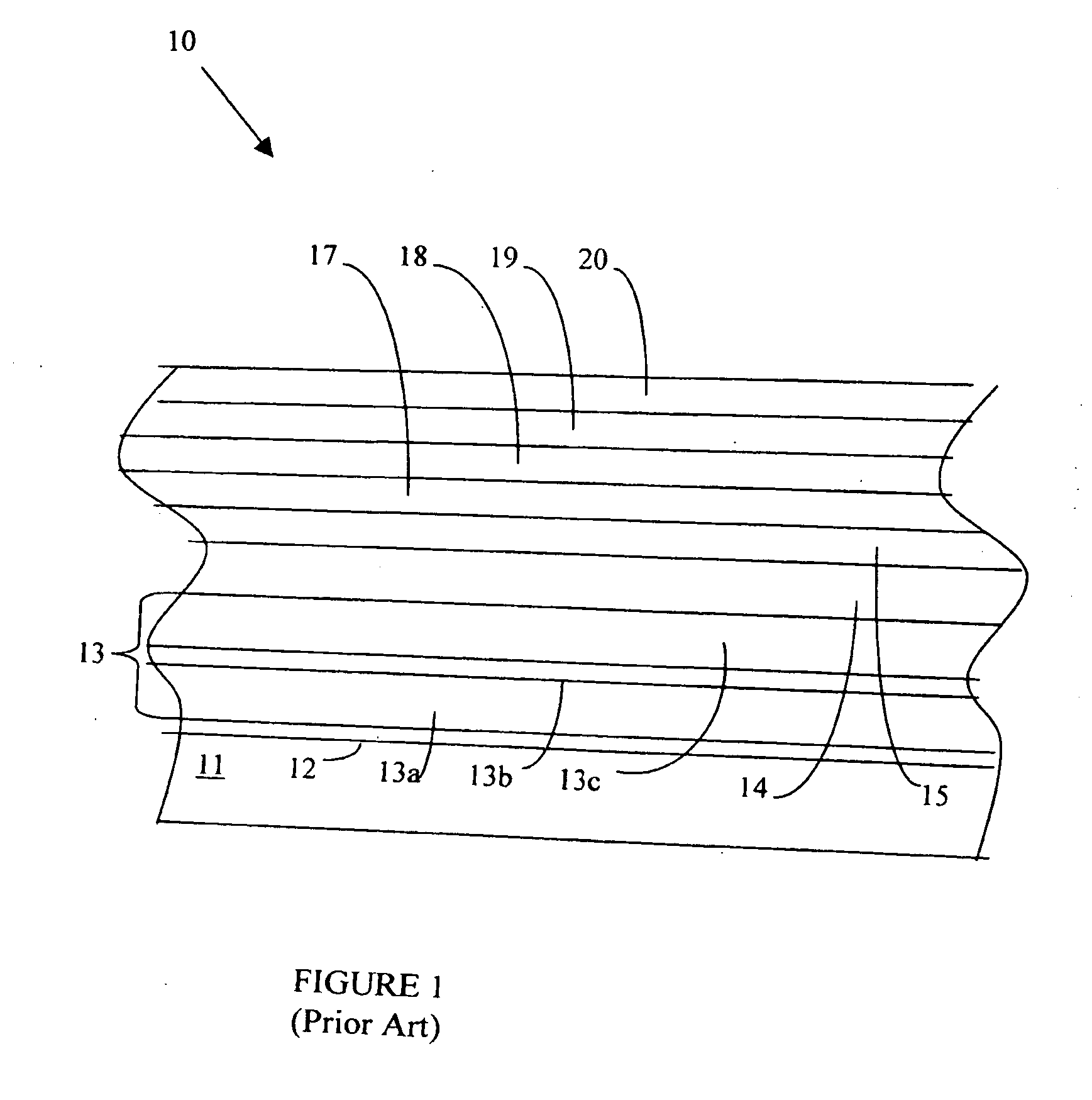
BACKGROUND OF THE INVENTION [0001]This invention pertains to perpendicular magnetic recording media and methods for making perpendicular magnetic recording media.[0002]FIG. 1 illustrates a prior art magnetic recording medium 10 used for perpendicular recording. Medium 10 comprises a substrate 11, an adhesion layer 12, a soft underlayer (“SUL”) structure 13, a Ta seed layer 14, a hexagonal close packed (“HCP”) RuCr30 alloy layer 15, a HCP Ru layer 17, a bottom magnetic HCP CoCr17Pt18(SiO2)2 alloy layer 18, a capping magnetic HCP CoCr16Pt18(TiO2)1.5 alloy layer 19, and a carbon protective overcoat 20. The <0001> axis (the C axis) of the HCP crystals of layers 18 and 19 preferentially orient vertically. Layers 14, 15 and 17 are provided to promote vertical orientation of the C axis and to enhance grain isolation in layers 18 and 19 when layers 18 and 19 are deposited which result in enhancing the coercivity Hc of magnetic layers 18 and 19.[0003]Layers 18 and 19 store magnetically...

Claims


Application Information

Patent Timeline
Patent Type & Authority Applications(United States)
IPC IPC(8): G11B5/706B05D5/12
CPCG11B5/7325G11B5/732G11B5/7379G11B5/736G11B5/737
Inventor JUNG, HONG-SIKBERTERO, GERARDOVELU, EMURKUO, MICHAEL CHENG-CHIACHARYA, B. RAMAMURTHYMALHOTRA, SUDHIR
Owner WD MEDIA
Learn More