
Stable lithium niobate waveguides, and methods of making and using same

a lithium niobate and waveguide technology, applied in the field of lithium niobate waveguides, and methods of making and using same, can solve the problems of waveguide instability, limitation of application, and performance degradation of lithium niobate waveguides prepared using conventional proton exchange techniques, and achieve no degradation in performance and performance.

Active Publication Date: 2012-05-29
THE AEROSPACE CORPORATION
View PDF10 Cites 11 Cited by
  • Summary
  • Abstract
  • Description
  • Claims
  • Application Information

AI Technical Summary

Benefits of technology

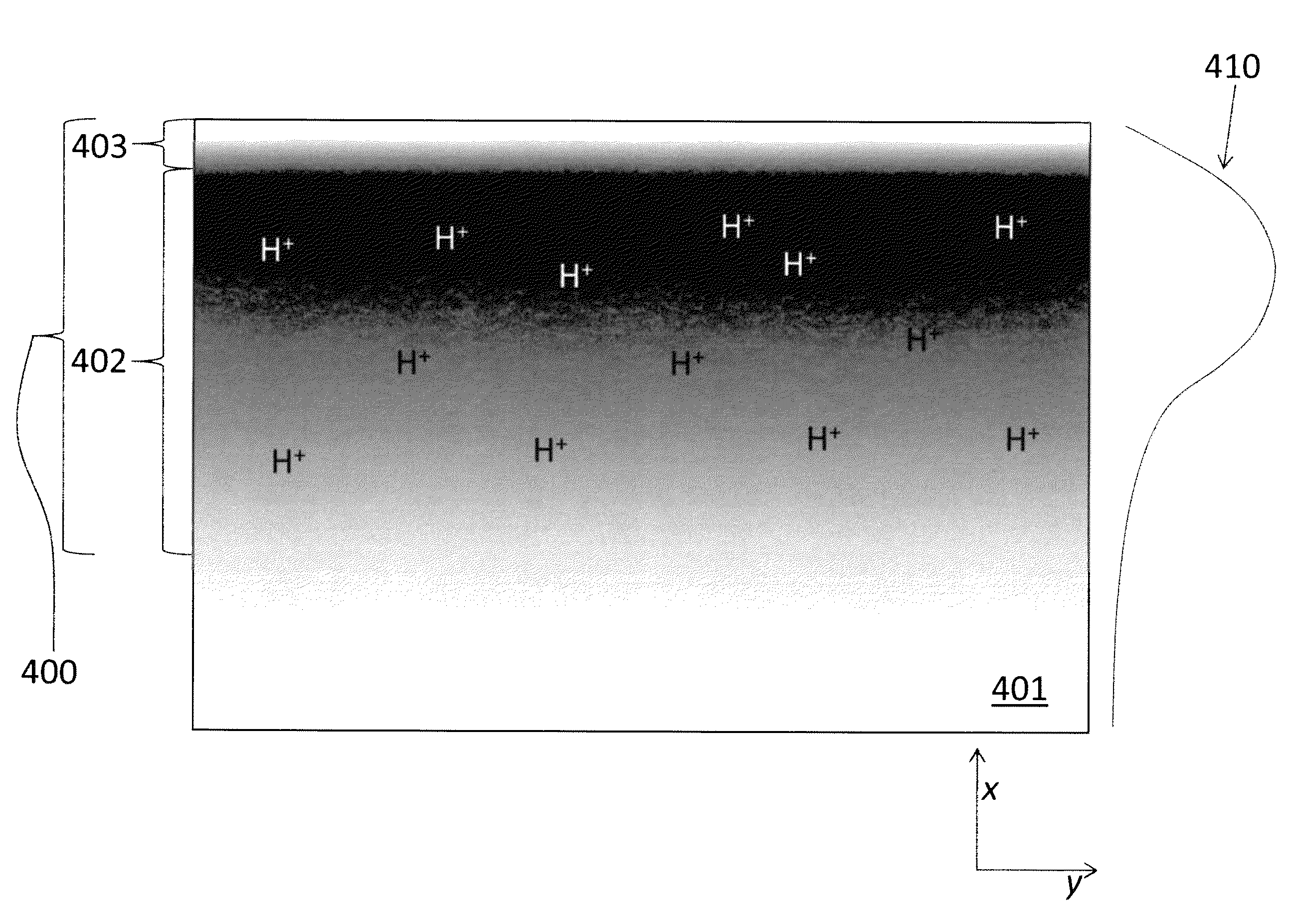
[0012]The present invention provides stable lithium niobate waveguides having improved stability, and methods of making and using same. Specifically, the waveguides may be fabricated using a plurality of steps, each of which inhibits the formation of performance-degrading defects. For example, a high-refractive index layer may be prepared using a “soft” proton exchange on a lithium ion substrate, in which an excess of lithium ions are provided to slow the proton exchange reaction, allowing more time for the protons to diffuse into the substrate and thus reducing defect-inducing stress. Such a proton exchange step may be followed by an annealing step, during which a predetermined vapor pressure of water is applied over the substrate. The vapor pressure of water may be selected to (a) inhibit dehydration of the substrate, reducing the formation of defects, and (b) provide a specified stoichiometric ratio of niobium to oxygen in the proton-exchanged layer. Such an anneal step may be followed by a sealing step, in which the substrate is exposed to a reverse proton exchange, which replaces protons near the upper surface of the substrate with lithium ions. This sealing step forms a high quality protective lithium niobate overlayer over the proton-exchanged layer, which inhibits degradation of the proton-exchanged layer during use.
[0021]In accordance with yet another aspect of the present invention, a method of using a waveguide includes providing a waveguide, the waveguide comprising a lithium niobate substrate having an upper surface, a soft proton-exchanged layer formed by exposing the lithium niobate substrate to a proton exchange solution including a proton exchange acid and a lithium salt of the proton exchange acid at a temperature of less than an atmospheric boiling point of the solution, followed by annealing the lithium niobate substrate under a vapor pressure of water preselected to inhibit protons in the substrate from forming water and evaporating from the upper surface of the substrate, and an overlayer comprising lithium niobate, the overlayer embedded between the upper surface of the lithium niobate substrate and the soft proton-exchanged layer, the overlayer inhibiting substantially all transport of protons from the soft proton-exchanged layer to the upper surface of the substrate; and operating the waveguide for greater than 100 days with substantially no degradation in performance and without the use of drift-compensation circuitry. For example, the waveguide may be operated for greater than one year with substantially no degradation in performance and without the use of drift-compensation circuitry.

Problems solved by technology

Lithium niobate waveguides prepared using conventional proton exchange techniques are vulnerable to performance degradation, limiting their application.
However, the resulting waveguide may be unstable due to stresses caused by the ion exchange process.
These stresses may damage the waveguide by causing crystal dislocations and / or cracks.
Such defects may arise, for example, because protons are smaller than the lithium ions they replace, causing the crystal lattice to shrink.
Any defects in the waveguide may serve as electron donors, proton diffusion pathways, and / or proton accumulation sites, which may detrimentally affect both the electrical insulation and the stability of the waveguide material.
Due to this instability, the performance of the crystal may degrade over time, including gradual changes in refractive index and / or electrical conductivity.
Such annealed waveguides are still susceptible to degradation under normal operating conditions, albeit much more slowly than non-annealed waveguides.
For example, by increasing the voltage, a satisfactory response may be obtained; however, once the degradation exceeds the ability of the electronics to compensate for such drift, the waveguide may no longer be capable of performing to specification.
Compensating for drifts in the electrical conductivity of the waveguide may also be difficult to achieve.
Disturbances of the crystalline lattice cause a substantial increase in conductivity, which allows space charges to accumulate near the electrodes, producing a drift condition.
The feedback circuitry required to adjust the applied voltage to compensate for drift in the refractive index and electrical conductivity of the waveguide may add significant expense and complication to the modulator circuit, may limit the switching speed of the device, and may limit the environments in which the device may be used.
Such pressurization may be both inconvenient and dangerous, particularly over extended periods of time.

Method used


Image

  • Stable lithium niobate waveguides, and methods of making and using same
  • Stable lithium niobate waveguides, and methods of making and using same
  • Stable lithium niobate waveguides, and methods of making and using same

Examples


Embodiment Construction

[0036]Overview

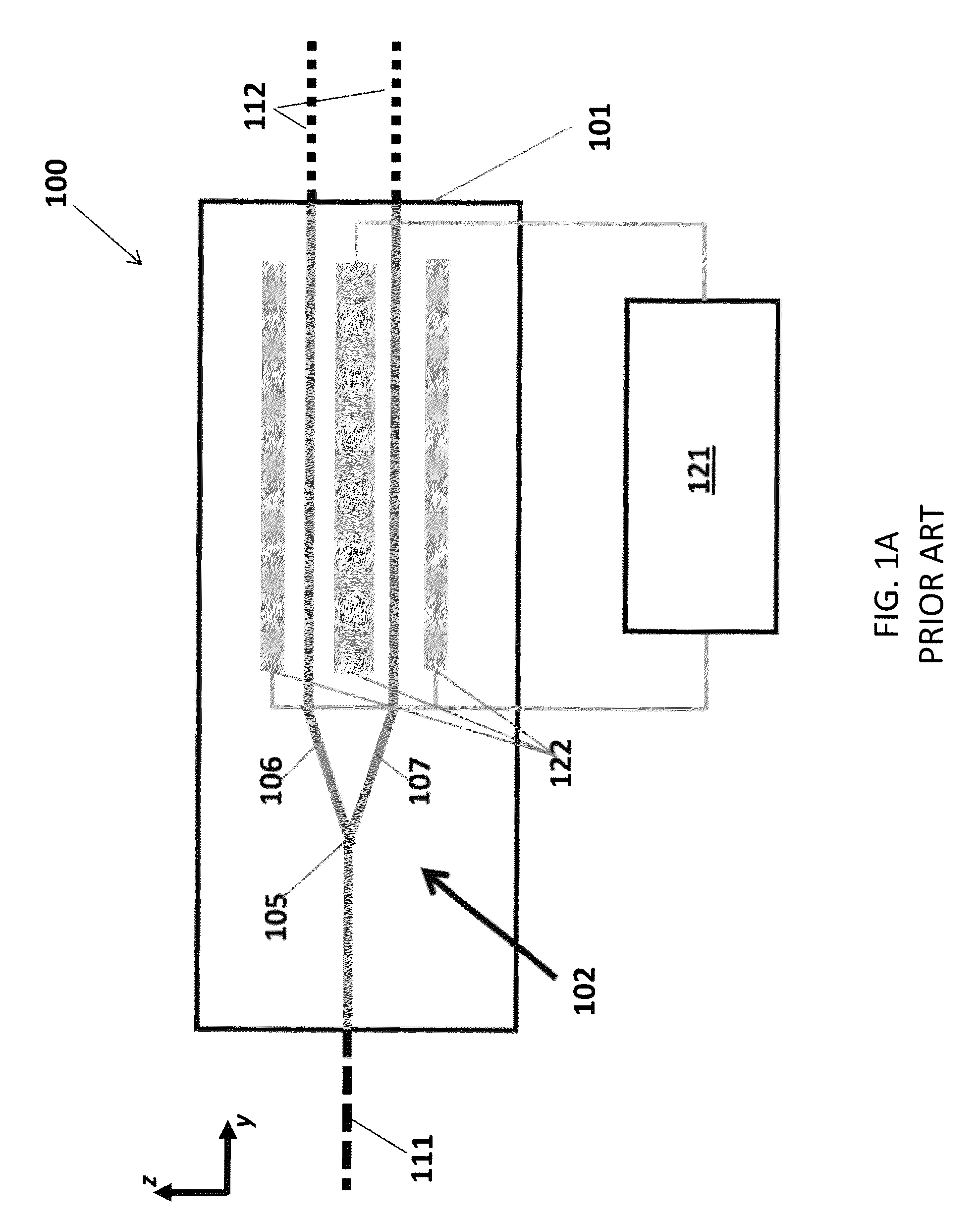
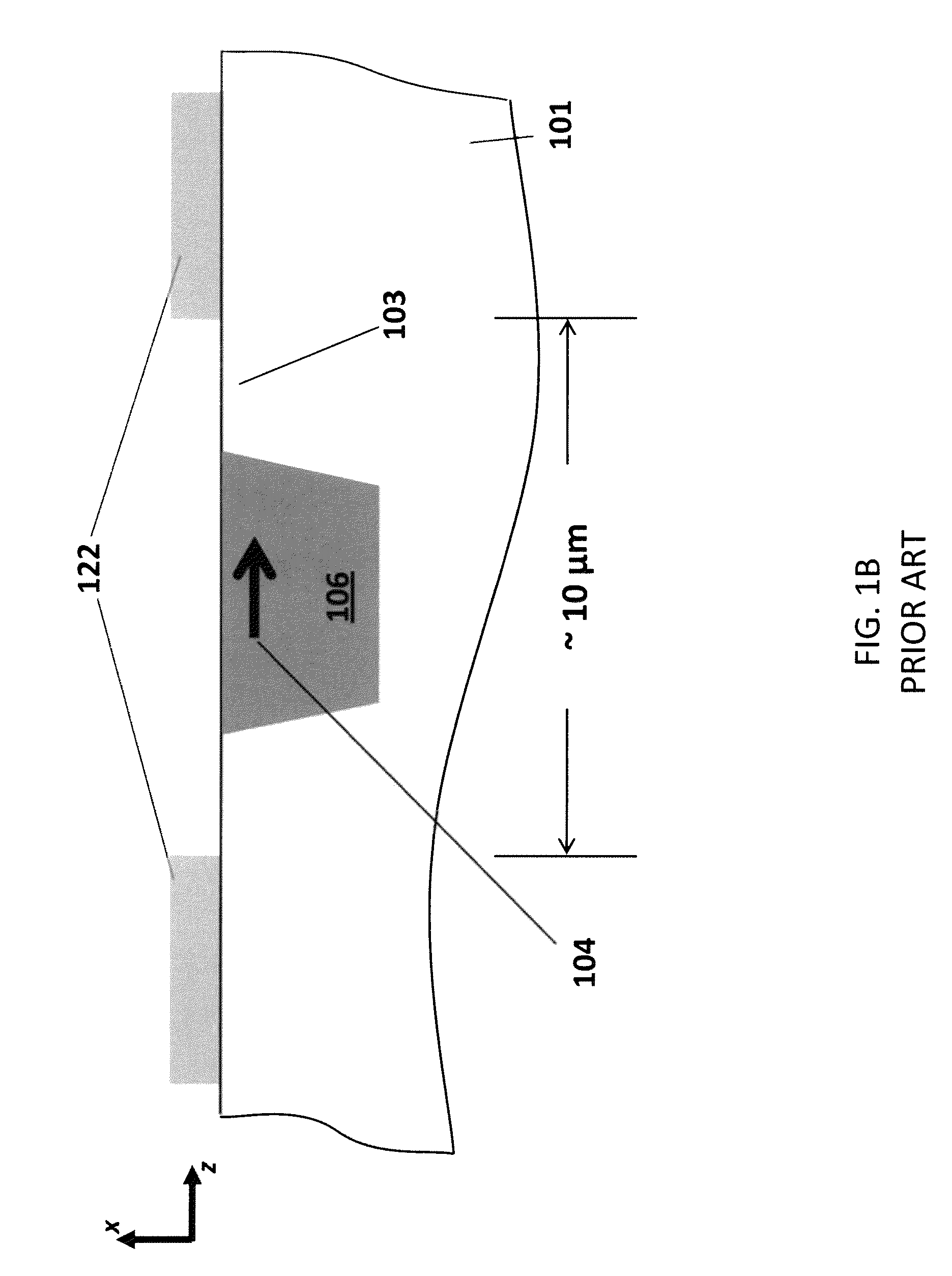
[0037]Embodiments of the present invention provide lithium niobate waveguides that have few, if any, defects in the crystalline lattice, and are stable under a wide variety of environmental conditions. Thus, in contrast to waveguides made in accordance with previously known methods, feedback circuitry need not be used to monitor the performance of the inventive waveguides and continually adjust the applied voltages to compensate for drifts in performance.

[0038]The waveguides of the present invention may be formed using a combination of steps that, together, reduce or eliminate many of the aforementioned problems associated with previously known lithium niobate waveguides, particularly drift in the refractive index and electrical conductivity, or complexity of fabrication. These steps include a “soft” proton exchange process for changing the refractive index of the lithium niobate substrate, in which an excess of lithium ions is provided. For example, a solution of lith...


PUM

PropertyMeasurementUnit
water vapor pressureaaaaaaaaaa

Abstract

The invention provides stable lithium niobate waveguides, and systems and methods for making same. In accordance with one aspect of the invention, a waveguide includes a lithium niobate substrate having an upper surface; and a soft proton-exchanged layer embedded within the substrate, the soft proton-exchanged layer formed by exposing the lithium niobate substrate to a proton exchange solution including a proton exchange acid and a lithium salt of the proton exchange acid at a temperature of less than an atmospheric boiling point of the solution, followed by annealing the lithium niobate substrate under a vapor pressure of water preselected to inhibit protons in the substrate from forming water and evaporating from the upper surface of the substrate. The preselected water vapor pressure may be between 0.1 atm and about 0.9 atm, for example, between about 0.4 atm and about 0.6 atm, in one embodiment about 0.47 atm.

Description

STATEMENT OF GOVERNMENT INTEREST[0001]This invention was made with Government support under contract FA8802-04-C-0001 awarded by the Department of the Air Force. The Government has certain rights in the invention.FIELD OF THE INVENTION[0002]This application generally relates to lithium niobate waveguides, and methods of making and using same.BACKGROUND OF THE INVENTION[0003]Electro-optically active devices have conventionally been prepared using lithium niobate (LiNbO3). As is familiar to those of ordinary skill in the art, lithium niobate has a lattice structure in which the lithium ions have a non-centrosymmetric position. In the absence of an electric field, this non-centrosymmetric position imparts the material with a net polarization. Applying an electric field to the lithium niobate shifts the position of the lithium ions, changing the net polarization, and refractive index, of the material. Thus, the phase of light propagating through the waveguide may be altered by applying ...

Claims


Application Information

Patent Timeline
Patent Type & Authority Patents(United States)
IPC IPC(8): G02B6/10
CPCG02B6/1345G02F1/225G02F2001/212G02F2202/20G02F1/212
Inventor MULLER, HEINRICH G.KIM, HYUN I.FORAN, BRENDAN J.
Owner THE AEROSPACE CORPORATION
Learn More